Dear Ray, and LAMMPS users,
Hi,
I’m using LAMMPS to simulate the failure behavior of my ceramic system. To make sure of the validity of structure, potential and etc I first tried to calculate the elastic constants using the codes that is available in Example directory. By doing so, I obtained the correct value for elastic constants. I also checked the lattice constants, and even P.E. of the structure and compared it with the literature and all of the works fine. Up to here everything was calculated in ( P P P ) as bulk material. Then I started a new simulation using ( P P S ) because I want to work on nanomembrane ( Finite thickness in z ). Then I used the below code:
#INITIALIZATION
units metal
boundary p p s
atom_style atomic
#atom_modify map array
#box tilt large
read_data Si3N4.in
pair_style tersoff
pair_coeff * * SiN.Tersoff N Si
------------------------- Minimization ---------------------------------
#replicate 10 6 5
compute stress all stress/atom NULL
compute stress1 all reduce sum c_stress[1]
compute stress2 all reduce sum c_stress[2]
compute stress3 all reduce sum c_stress[3]
compute stress4 all reduce sum c_stress[4]
compute stress5 all reduce sum c_stress[5]
compute stress6 all reduce sum c_stress[6]
thermo 1
thermo_style custom step lx ly lz press pxx pyy pzz pxy pxz pyz pe temp
fix 2 all box/relax x 0 y 0 vmax 0.001
min_style sd
minimize 1.0e-25 1.0e-25 100000 100000
unfix 2
write_data Min.in
------------------------- Equilibration ( NPT ) ---------------------------------
reset_timestep 0
velocity all create 100 277387
fix 1 all npt temp 100 300 0.1 x 0 0 1.0 y 0 0 1.0 drag 0.3
thermo 1000
thermo_style custom step lx ly lz press pxx pyy pzz pxy pxz pyz pe temp
dump q2 all custom 1000 dump.npt.*.cfg id type xs ys zs c_stress[1] c_stress[2] c_stress[3] c_stress[4] c_stress[5] c_stress[6]
#dump_modify q2 element N Si
run 100000
undump q2
unfix 1
write_data EQ2.in
------------------------- Deformation ---------------------------------
reset_timestep 0
variable tmp equal “lx”
variable L0 equal {tmp}
print "Initial Length, L0: {L0}"
fix 1 all npt temp 300 300 0.1 y 0 0 1.0 drag 0.3
fix 2 all deform 1 x erate 0.0001 units box remap x
variable strain equal “(lx - v_L0)/v_L0”
variable p1 equal “v_strain”
variable p2 equal “-pxx/10000”
variable p3 equal “-pyy/10000”
variable p4 equal “-pzz/10000”
variable p5 equal “-pxy/10000”
variable p6 equal “-pxz/10000”
variable p7 equal “-pyz/10000”
thermo 5000
thermo_style custom step v_strain temp v_p1 v_p2 v_p3 v_p4 v_p5 v_p6 v_p7 ke pe press
dump 1 all custom 5000 dump.tensile.*.cfg id type xs ys zs c_stress[1] c_stress[2] c_stress[3] c_stress[4] c_stress[5] c_stress[6]
#dump_modify 1 element N Si
fix def1 all print 500 “{p1} {p2} {p3} {p4} {p5} {p6} ${p7}” file Final.dat screen no
run 150000000
write_data Def.in
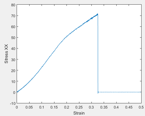
But, the stress strain curve that I obtain is not in good agreement with Literature, especially the stress value at fracture point is too high. As you can see I used -Pxx as the true stress. I wonder if you could please help me out with it.
Thanks,
Ali