I have a Cu Single Crystal oriented as “” x=[1 1 0], y=[-1 1 1], z=[1 -1 2]."" the coordinates of which i have defined through MATLAB to create one edge dislocation. What i have done is-
each atom is placed at ““a/sqrt(3)””" distance from previous one along the y axis, y- [-1 1 1]
““a/sqrt(6)””" distance from previous one along the z axis, z---- [1-1 2]
““a/sqrt(2)-b/2"”” distance from previous one along the x axis, x—[1 1 0] for upper half crystal,
““a/sqrt(2)+b/2"”” distance from previous one along the x axis, x—[1 1 0] for lower half crystal,
where b=burger vector= a/sqrt(2) for fcc.
Visualizing through ATOMEYE shows like the images i am attaching. The box is not filled completely, as it should be… So, is there a ““vacuum gap”” left in the box?? How do i overcome it???
I gave “lattice fcc 3.615 orient x 1 1 0 orient y -1 1 1 orient z 1 -1 2” before the read_data command, but in vein…!!!
please use a descriptive subject line when posting your e-mails.
Dear All,
I have a Cu Single Crystal oriented as "" x=[1 1 0], y=[-1 1 1], z=[1 -1
2]."" the coordinates of which i have defined through MATLAB to create one
edge dislocation. What i have done is-
each atom is placed at ""a/sqrt(3)""" distance from previous one along the y
axis, y- [-1 1 1]
""a/sqrt(6)""" distance from previous one along the z axis, z---- [1-1
2]
""a/sqrt(2)-b/2""" distance from previous one along the x axis, x---[1 1
0] for upper half crystal,
""a/sqrt(2)+b/2""" distance from previous one along the x axis, x---[1 1
0] for lower half crystal,
where b=burger vector= a/sqrt(2) for fcc.
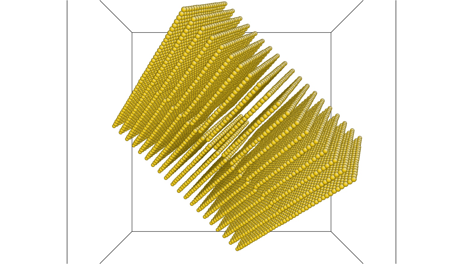
Visualizing through ATOMEYE shows like the images i am attaching. The box is
not filled completely, as it should be.. So, is there a ""vacuum gap"" left
in the box?? How do i overcome it???
that is up to your matlab script and not a LAMMPS problem.
I gave "lattice fcc 3.615 orient x 1 1 0 orient y -1 1 1 orient z 1 -1 2"
before the read_data command, but in vein..!!!!!!
the lattice command has no impact whatsorever on a data file
or coordinates or anything for as long as they are provided in
direct x,y,z coordinates.
its sole purpose is to prove a simplified measure to identify
positions that are commensurate with a given lattice.
the simulation cell in LAMMPS is *always* oriented in a
very specific way in space, as explained in the documentation.
You have created a data file using a matlab script. If you are using
a data file, then usually, you do not need the "lattice" command.
In my opinion, the easiest thing to do is to modify your matlab script
to generate a much larger rotated box of atoms and throw away atoms
which lie outside your simulation's rectangular boundary box.
I sometimes prefer to create a data file because it gives you more
manual control over where each atom is located. But it is not the
only way. Alternately In your case, however, it might be easier to
avoid "data" files and instead use native lammps input script commands
"lattice", "region", "create_atoms" to fill the space in your
simulation box with two different lattices. (I have never tried to do
this, but I believe it is possible.) http://lammps.sandia.gov/doc/create_atoms.html http://lammps.sandia.gov/doc/region.html http://lammps.sandia.gov/doc/lattice.html
However your main problem is geometrical: What your picture shows is
not an edge dislocation, but two different crystal lattices with the
same orientation and different lattice spacing. That's fine. When
you minimize/relax the coordinates of the atoms, you should get an
edge-dislocation. However you need to think about periodic boundary
conditions before you place these two crystals in your simulation's
periodic boundary box. The boundary between these two crystals is
guaranteed to intersect your simulation-box in multiple places. You
need to insure that the boundary between the two crystal types remains
continuous/flat at each face of the simulation box with it's neighbor.
(I suspect you don't want to end up with a "zig-zag" shape
...NNNNNN... I think you want the boundary between the two crystal
types to be flat.) Otherwise, even after you fill the remaining space
with atoms, I worry that you may end up with more dislocations than
you thought.
Be sure to draw this on paper in 3D and think about where the
boundaries will go beforehand. This problem should not be too
difficult to solve, (but you might need a few sheets of paper and a
little free time).
Once you have figured out how to fill the simulation box with atoms,
you will want to look at your system in 3D to make sure it is correct.
I don't know how to use AtomEye, but if you have created a "data"
file, then you can view it in VMD/topotools. VMD allows you to draw
the simulation's periodic boundary box and view multiple periodic
images of your system. This is very useful for checking for problems
at the boarders. I have attached some instructions for how to do this
using VMD/topotools. (See "README_visualize.txt")
...actually, when I look at your picture again I guess it does look
like an edge-dislocation. I should not have said that. I hope this
did not distract from the larger point I was trying to make.
By the way, it was very helpful that you included a picture with your
post. Thanks!