I have attached a revised property definition for generalized-planar-fault-energy-relaxed-hexagonal-crystal, where there would be separate definitions for cubic and non-relaxed crystals. For ease of discussion, I have attached hcp and fcc example calculations.
Within the EDN file, keys from “short-name” to “wyckoff-coordinates” are largely copied from other property definitions. The remaining keys are those specific to fault energy calculation, which do the following:
Define the fault plane
“bravais-miller-indices-fault-plane-family”
“bravais-miller-indices-fault-plane-position”
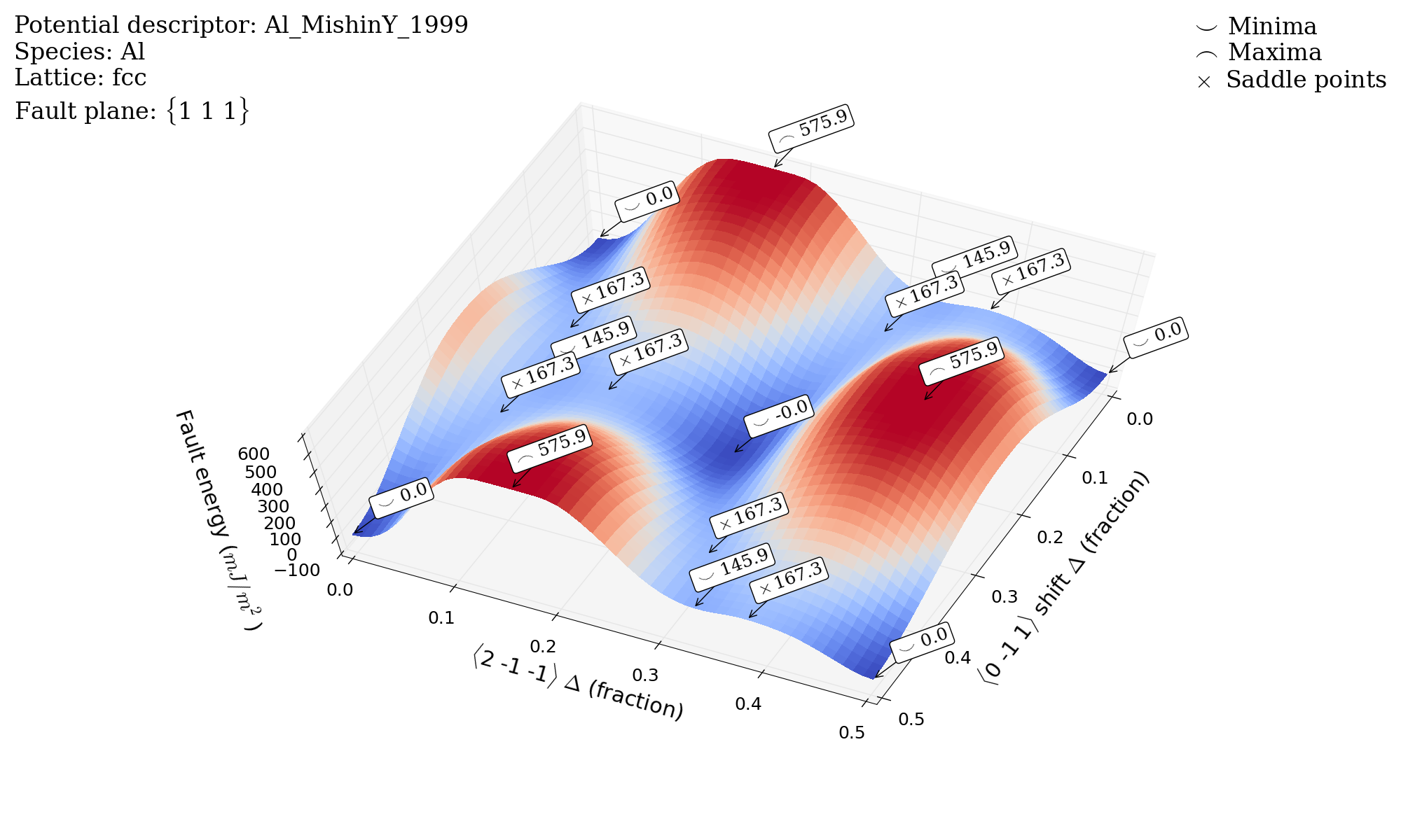
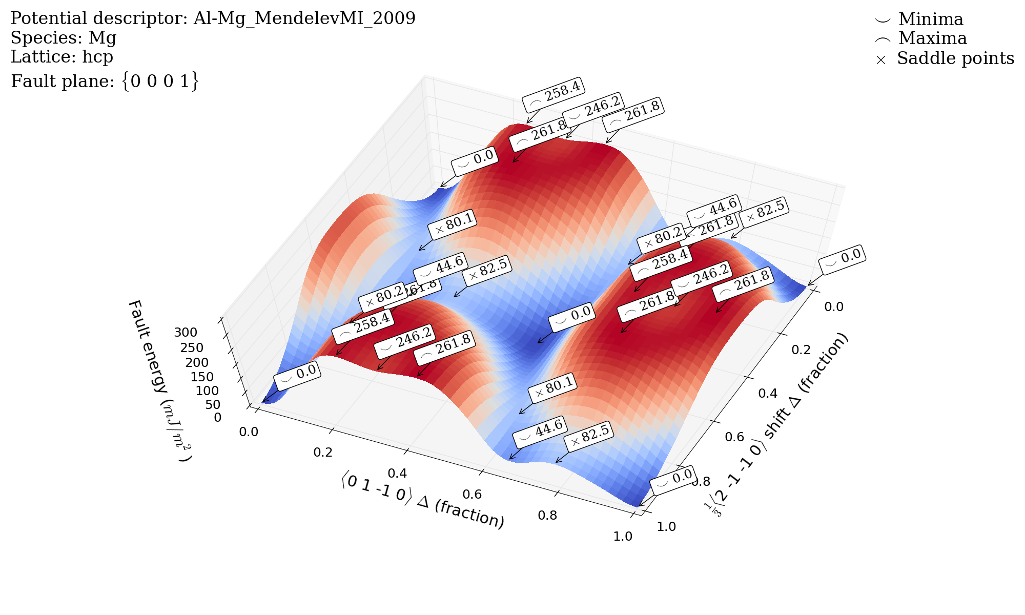
These define the fault plane family (e.g. {1 1 1} in fcc, {0 0 0 1} in hcp) and a vector pointing to the cutting plane position (e.g. 1/6[1 1 1] in fcc, 1/4[0 0 0 1] in hcp).
Define the fault energy surface
“bravais-miller-indices-inplane-unit-cell-shift-vector-1”
“bravais-miller-indices-inplane-unit-cell-shift-vector-2”
“fault-plane-shift-vector-fraction”
“fault-plane-energy”
These define direction vectors of inplane displacement, fractional displacement along those vectors, and fault the energy for a given displacement.
Note: The user is given the flexibility of choosing the shift vector and shift fraction. Using fcc as an example, one could choose:
a shift vector 1/2[0 -1 1] and vary fractional displacement from 0.0 to 1.0
a shift vector [0 -1 1] and vary fractional displacement from 0.0 to 0.5
Define extrema identified within the fault energy surface
“fault-plane-shift-vector-fraction-extrema”
“fault-plane-energy-extrema”
“fault-plane-extrema-type”
These define the location, type, and energy associated with local extrema identified within the fault energy surface (e.g. local maxima, local minima, and saddle point). See labels in attached figures. I added this feature to the calculation because I thought it useful as certain saddle points and local minima correspond to unstable and stable stacking faults in certain cases. I have two questions: Should this be part of the property? Is this a useful feature?
Define simulation boundary conditions in the direction normal to the fault plane
“boundary-condition-fault-plane-normal”
I look forward to further discussions. I wanted to keep this email brief for those new to the discussion.
Without getting into the real content of this Property Definition, one thing I can say is missing is that, in the Wyckoff description of the crystal, you need to have a “wyckoff-species” key in addition to “wyckoff-coordinates” and “wyckoff-multiplicity-and-letter.” This is necessary in order to unambiguously define the structure in the multispecies case. This key was mistakenly omitted from the relevant properties when you copied them over, but is there now. For example, see https://openkim.org/properties/show/2014-04-15/[email protected]/cohesive-potential-energy-cubic-crystal#key-wyckoff-species. Apologies for this oversight.
This looks nice. I think your "fault-plane-extrema" entries are good.
The only issue I see (modulo the comments from Dan about the Wyckoff description) is that I don't completely understand the "boundar-condition-fault-plane-normal" key. (The property description seems indicates that this should always be "relaxed free surface" ?)
I have attached a revised property definition for
generalized-planar-fault-energy-relaxed-hexagonal-crystal, where there
would be separate definitions for cubic and non-relaxed crystals. For
ease of discussion, I have attached hcp and fcc example calculations.
Within the EDN file, keys from "short-name" to "wyckoff-coordinates"
are largely copied from other property definitions. The remaining keys
are those specific to fault energy calculation, which do the following:
# Define the fault plane
"bravais-miller-indices-fault-plane-family"
"bravais-miller-indices-fault-plane-position"
These define the fault plane family (e.g. {1 1 1} in fcc, {0 0 0 1} in
hcp) and a vector pointing to the cutting plane position (e.g. 1/6[1 1
1] in fcc, 1/4[0 0 0 1] in hcp).
# Define the fault energy surface
"bravais-miller-indices-inplane-unit-cell-shift-vector-1"
"bravais-miller-indices-inplane-unit-cell-shift-vector-2"
"fault-plane-shift-vector-fraction"
"fault-plane-energy"
These define direction vectors of inplane displacement, fractional
displacement along those vectors, and fault the energy for a given
displacement.
Note: The user is given the flexibility of choosing the shift vector
and shift fraction. Using fcc as an example, one could choose:
* a shift vector 1/2[0 -1 1] and vary fractional displacement from 0.0
to 1.0
* a shift vector [0 -1 1] and vary fractional displacement from 0.0 to
0.5
# Define extrema identified within the fault energy surface
"fault-plane-shift-vector-fraction-extrema"
"fault-plane-energy-extrema"
"fault-plane-extrema-type" These define the location, type, and energy
associated with local extrema identified within the fault energy
surface
(e.g. local maxima, local minima, and saddle point). See labels in
attached
figures. I added this feature to the calculation because I thought it
useful
as certain saddle points and local minima correspond to unstable and
stable
stacking faults in certain cases. I have two questions: Should this be
part
of the property? Is this a useful feature?
# Define simulation boundary conditions in the direction normal to the
fault
plane "boundary-condition-fault-plane-normal"
I look forward to further discussions. I wanted to keep this email
brief for those new to the discussion.
Hi Zach,
This looks nice. I think your "fault-plane-extrema" entries are good.
The only issue I see (modulo the comments from Dan about the Wyckoff
description) is that I don't completely understand the
"boundar-condition-fault-plane-normal" key. (The property description
seems indicates that this should always be "relaxed free surface" ?)
No, the relaxation refers to the atoms with respect to the interface.
Interface conditions: atoms relaxed normal to plane, or unrelaxed
Normal boundary conditions: non-periodic relaxed, non-periodic rigid
block, etc.