I’d encourage you to match the de Cruz set-up exactly if you can. From your visualization with very nearly hexagonal packings in many places, I wouldn’t be surprised by your velocity profile. As Axel states, its probably due to ordering near your walls. To answer some of your other points:
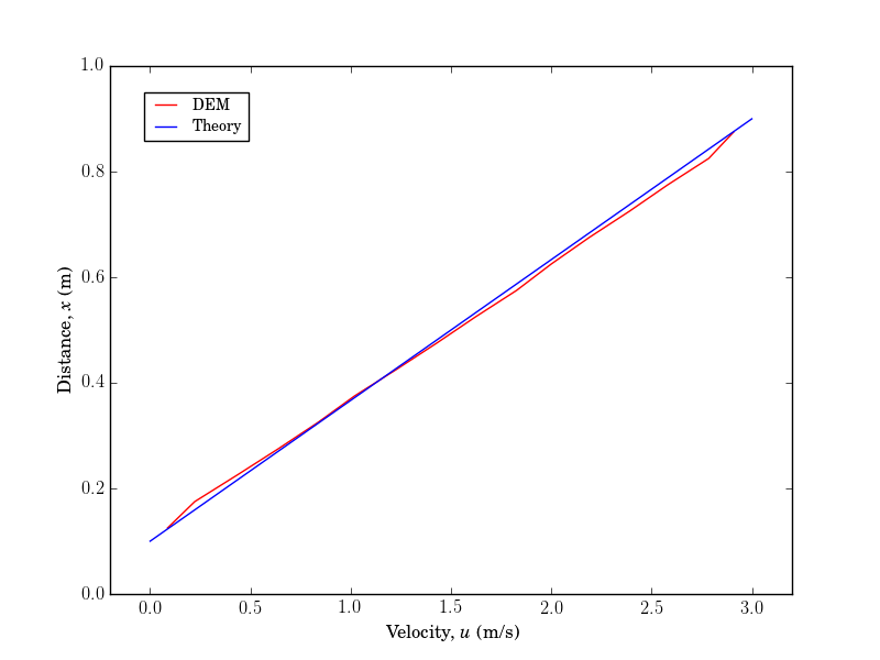
There seems to be some kind of crystallization near the walls for the LAMMPS simulation, although the central flow region seems to be fairly linear. The daCruz case also contains no friction - presumably this means that the particles have no tangential force on them and if there is also no tangential damping, they cannot rotate. Could a tightly packed wall encourage crystallisation if the particles cannot rotate free of this zone - like raking the particles through the flow?
You do not require friction to have crystallization. However, friciton on the particle DOES affect many things in these systems from anisotropy in ordering, stress, instabilities, etc. I suggest matching these between comparisons as best you can.
I noticed that the literature ignores the zones close to the wall and has possibly rescaled the profile to show only the linear zone, but I’m not sure if that is the reason. Do you know what could cause this problem?
Its typically ignored for exactly the reason you are seeing it - they are interested in ‘statistically homogeneous simple shear’. Your walls are rigid and ordered, why would you expect confined particles to not have similar ordering near them. Most of these ideas are just geometry - how many ways can additional circles be arranged in a space if there are additional particles that cannot be moved - compared with a case where there are no immobile circles.
Presumably increased polydispersity would cause more slippage at the wall and less polydispersity would cause more crystallisation?
The idea that polydispersity decreases crystallization is generally accepted in the DEM community. Slippage is a bit more vague in my opinion.
But why would re-ordering the wall particles influence the velocity profile? - but it’s true that the wall particles are added first in order, then the flow particles are randomly placed between them. Should the wall particles be added with random id numbers?
The only thing affecting your velocity profile is that you essentially have a non-yielding solid layer near the walls that moves at roughly the same velocity - That is what your velocity profile tells me. From your input script, re-ordering your commands should not change a thing - this is VERY likely NOT an averaging/implementation error. You’re welcome to confirm this. Try seeing what your velocity profile looks like if you shear with a triclinic box instead, if you still require more convincing.
Also, why is there an excluded volume near the walls? - the velocity profile is being computed for all atoms in the simulation.
If you still have any questions on what is meant by ‘excluded volume,’ please do some searching - if your dealing with DEM (relatively hard particles) you will benefit from understanding what this means.
As a side point, the primary benefit of shearing with walls is that you can easily control the imposed normal force without manipulating the spaces in between relatively hard particles throughout the domain as is done with a barostat. You don’t need to use them if that’s not your concern. Gravity can also be a concern depending on the problem.
HTH,