A short motivation for my question (can be skipped)
I am currently doing a project where I stretch a graphene sheet and measure frictional properties for various cut patterns applied to the sheet. A main concern is therefore that the sheet can get to porous and rupture under a significant amount of stretching. Thus I want to implement a way of detecting whether a sheet is ruptured and stop the simulation early using the fix halt command and print a rupture flag to file. Due to my current framework it is desirable to keep this detection process in LAMMPS and any post-processing.
My current method keeps track of the strain (in the stretch direction) and the number of clusters in the sheet atom group. Hence I can detect ruptures as a distinct drop in the strain value or if I the number of clusters exceeds one. While this captures most of the ruptures occurring It fails to detect ruptures where only parts of the sheet ruptures.
The only solution I can think of to eliminate this problem is to somehow get the nearest neighbours for each atom and make sure that these remains within a reasonable distance during the simulation.
The technical specifications of my question
Is it possible to retrieve information about nearest neighbours in the form of a per atom array. This information should be available in the neighbor list, but I cannot figure out how to access this information during simulation time.
If possible, I want to gather the nearest neighbours (within a cut-off) at a given initial timestep. Then at a later timestep, I would like to verify that these nearest neighbours is still within a certain distance to their respective atoms. I realize that this computation can be rather heavy, but I do not need to evaluate this condition often, and thus I’m not really concerned about the computational costs of this.
Do you have any ideas to solve this problem or get around it in some other way. Thanks in advance for reading through a rather long post.
No, it is not. The neighbor list only stores which atoms are within a given distance. There is no sorting by distance. That would require quite a bit of extra work, storage, and bookkeeping. The neighbor list storage is already the largest memory consumer of a classical MD simulation.
You don’t really need to know the nearest neighbors, you only need to know how many atoms are within a given cutoff distance from each atom. This could be done with the compute coord/atom command — LAMMPS documentation
Thanks for the fast reply @akohlmey. It makes sense what you say about the neighbour list, but is there any option to go access the neighbor list and pick out atom ID’s corresponding to atoms within a given distance, or is this out of reach at simulation time?
Blockquote
You don’t really need to know the nearest neighbors, you only need to know how many atoms are within a given cutoff distance from each atom. This could be done with the compute coord/atom command — LAMMPS documentation
I have tried using the coordination number in an earlier approach, but I believe that it is insufficient to perform a bullet proof detection algorithm. When the sheet ruptures the atoms involved is often reattaching to other parts of the sheet and thus the coordination number may be unchanged when only calculating this at a sparse amount of timesteps. If I consider the condition for every timestep (ignoring the computational cost for now) the coordination number will still change due to fluctuations and buckling of the sheet as it is stretched. Also, some of the sheets simulated has fringes do to the nature of the cut patterns, and this leads to oscillations in coordination number for those parts. If I can get the nearest neighbours before the fringes start to “flap around”, I would know which atoms to require to be nearby and this should not be a problem.
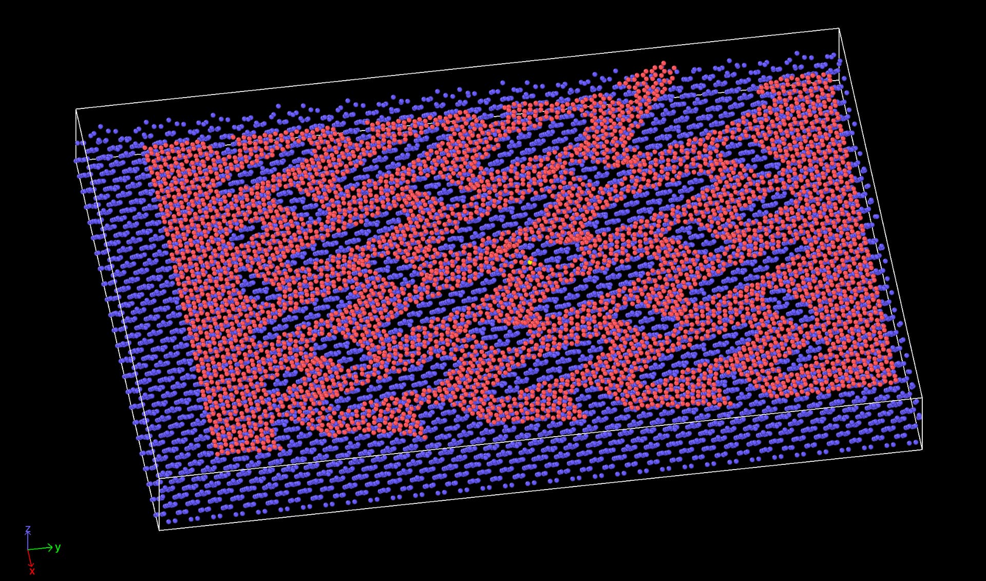
In order for you to get a better picture of the system I have attached a screenshot at a moment where the sheet (red atoms) is partly ruptured, which is seen in the top right part of the image. We also see that it has has reattached to another part of the sheet through the periodic boundary.
According to your original description, you just need to define a condition where you can stop the simulation. I think with a sensible choice of cutoff, you can reduce the amount of fluctuations. And to reach a condition to say when to stop, you would need to reduce this to a single number, so you would either have to compute the sum or minimum of the number of atoms within the coordination number cutoff. For that you should also have to have a threshold. If you use the sum and wait for a certain drop, I think that is a pretty good detection.
What you describe as a concern seems to me overly complex and not suitable for all cases. For describing structure, it should not matter where atoms come from. Your metric would detect when two atoms swap their places as a rupture, but it isn’t.
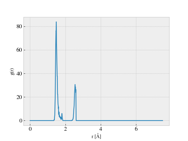
A good way to detect the suitable cutoff distance would be to compute the radial distribution function.
Typically, you want to pick a distance where the g(r) has a minimum.
Thanks again for the detailed and quick response. I see your point about the coordination number being useful when implemented with the right cut-off and evaluated at a reasonable interval. I might give this another shot, all though I found it unstable at last attempt.
My concern is really that the parameterization of the coordination number rupture condition might be tricky, and it is hard to ensure that it applies for a variety of different cut patterns corresponding to different rupture dynamics. My previous method by looking at the stress drop seemed to work fine until I tried a different sheet size, and my hope was really to avoid this continuing tweaking of the condition parameters. I’m going to simulate a lot of different cut patterns and hence I cannot verify that the rupture detection was successful for all of them.
Blockquote
What you describe as a concern seems to me overly complex and not suitable for all cases. For describing structure, it should not matter where atoms come from. Your metric would detect when two atoms swap their places as a rupture, but it isn’t.
I’m simulating the sheet at quite low temperature (in the 100K - 300K range) and I haven’t observed any atom swaps in my simulations so far. Thus, if I require the original neighbors to be within a distance of, lets say 3 times the original cut-off distance defining the neighbours in the first place, I think this would be a solid rupture classifier. But I guess your are recommending other methods as this is perhaps not accessible?
The kind of monitoring that you want to use would require some significant programming. Either directly in C++ or via the library interface using python code.
Blockquote
The kind of monitoring that you want to use would require some significant programming. Either directly in C++ or via the library interface using python code.
Roger that. I will try to make the best use of the tools available in Lammps at runtime then.
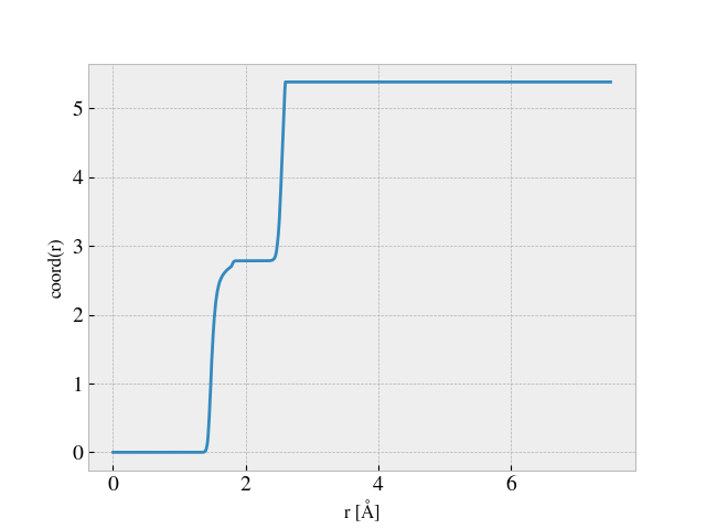
What cutoff are you referring to? 3x seems excessive and I don’t see a physical motivation for that. What I would look into is the first shell of neighbors. That is where the drop will be the most drastic for obvious reasons. The first shell can be easiest characterized by looking for a deep minimum after the first peak in the radial distribution g(r) of the original sheet. Using a (deep) minimum in the g(r) graph leads to requiring a significant change in geometry before you see a significant change in the coordination number. You can easily verify this by also outputting and plotting the coordination number as it is determined by compute rdf in LAMMPS. The further out you go (e.g. second or third shell) the less “stable” the structure is and the less sensitive this measure is.
Since you are stretching your system, it may be worth following the g(r) graph for a few test runs of different systems at a different degree of stretch and then perhaps push the desired cutoff for coordinations numbers somewhat to a larger value to not be too sensitive when the structure is still intact.
The 3x cutoff was a rough estimate since I believe that my initial wanted approach would not be very sensitive to the cutoff values. When the sheet ruptures, some of the atoms usually travels 10+ Å, and If you actually evaluated whether all atoms had their respective initial nearest neighbours within some distance, I suspect that this could probably be detected successfully for a variety of cutoff choices. But I do agree that an analysis of the RDF would be the logical way to determine a suitable cutoff.
I agree, but the potential problem is that the local “string-like” structure of the cutted sheet makes the change in the coordination number quite small under local ruptures. That is, when one of these “strings” rupture (as shown in the previously posted image) it is only 2-4 atoms within this first shell group that is displaced. The sheet has roughly 2k atoms at the moment (I might use more later) yielding a possible change of the coordination number average on the order 0.1% during a minimum rupture. Note that the minimum value of the coordination number is not useful here as some of the edges is dangling which gives a constant minimum of 1.0 for the coordination number.
I tried this by computing the RDF analysis as shown in the following images.
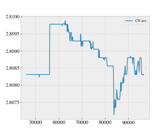
From this I defined a coordination number cutoff equal to 2.2 Å, for which I tracked the coordination number during a simulation starting from the point where the sheet is already stretched to the desired length and then dragged along the substrate. This yielded the following plot. The axis is missing since this was done on the fly, but we timesteps on the x-axis and average coordination number on the y-axis.
Here one can successfully identify the local rupture happening at the global minimum of the CN shown in the plot above (around timestep 8300-ish). By choosing a drop tolerance of 0.001 of the overall maximal value of the average CN graph I was able to detect this at runtime. However, in the time leading up to the rupture point the CN rises a bit and it shows that the possible fluctuations in the CN value might be very big in comparison to that of the chosen CN drop threshold. Thus, I worry that this is indeed very sensitive to threshold choices, and that it might be inaccurate for other cases.
This sound like a clever improvement, but I would need to implement some sort of automatic adjustment as I cannot anticipate the range of systems that I am going to simulate. This is eventually in the hands of a GAN network.
Once again @akohlmey, thanks for taking the time to answer these questions. I really appreciate the feedback!
Hi @srtee, thanks for the input. I think the idea behind this is reasonable, but I’m afraid that velocity is a too unstable quantity to use for the halt condition. The max velocity might spike due to atom fluctuation, and I’m very skeptical that any good threshold could be made for this.
Additionally this also adds the demand of computing the max velocity at almost every timestep as I might miss the rupture event happening otherwise. For the current methods discussed the values addressed is changed in a more permanent manner after the rupture event.
The maximum velocity is very easily computed using compute reduce, and the cost per processor per step would be N/P compares + 1 float over MPI, which is far smaller than e.g. PPPM. Furthermore I suspect the variance of velocities should be fairly well-defined for a set of thermalized bonded atoms. But it’s your call.
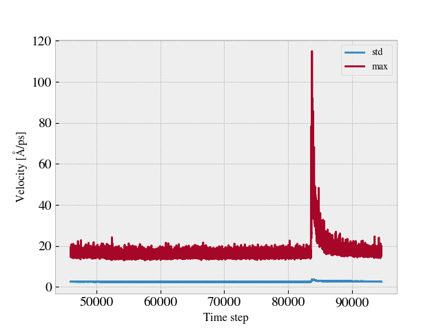
Hmm… I might have been to quick to condemn this idea. I’ve tried it out for the example case used in the earlier post, and I must admit that it seems surprisingly promising. By computing the velocity norm sqrt(vx^2 + v^2) in the xy-plane of the sheet and watching the max value and the standard deviation (std) the local rupture event is quite prominent as seen in the following plot.
I will run some more test to see if this generalizes well for other rupture events. If that is the case, I guess I could simply define a threshold relative to the standard deviation of the velocities. Thanks @srtee for pointing this out.
No problem. You might even get your monitoring “for free” if you have a thermostat running. The thermostat will have a temperature compute which calculates the system’s total kinetic energy at every step, and that quantity should also spike in a rupture.
But if you have a working compute reduce max example you should be able to check for yourself that its cost is quite small.
Thanks for the advice, this might be useful to keep in mind for future use. Unfortunately, my thermostat is only applied to the atoms surrounding the inner part of the sheet of interest. So I have to go with the additional compute this time.
I just want to give an update on the problem since this might be interesting for any future readers. I’ve tried the max velocity condition for various systems now, and it is does a good job for predicting rupture during the stretch phase, but the previous method using stress was also stable for that.
However, it struggles a bit in the drag phase of the simulation. As the sheet slides against the substrate it experiences a stick-slip kind of motion arising from the frictional forces between the sheet and substrate. This makes the max velocity spike even though I subtract the center of mass (COM) velocity from the max value. I guess that all atoms of the sheet does not move at the exactly same time, and this makes it is hard to avoid a spike in the max velocity. One might be able to avoid this be applying some extra condition to account for the rapid movement of the whole sheet, but I found it too complicated and unstable to sort out.
Instead I discovered that the MSD calculation with subtracted COM position and average reference position,
compute 1 upper msd com yes average yes,
is a better candidate, with the condition simply being that the values are below some threshold. This passes all test so far, and I conclude that this is the best solution among the discussed ones so far (for the drag phase). Note that for the stretch phase this is not suitable as the atoms travels a considerable distance while the COM stays more or less constant. For that the stress or max velocity metric is the better choice.
Another idea: Create a 2d grid and calculate number density of carbon atoms in each chunk. When a rupture happens, the number density should drastically change (judging from the picture in the 3rd post).
Interesting suggestion @mkanski, this might be a good solution also. However, when the sheet is dragged along the substrate I would have to update the 2D grid accordingly. Since the cuts in the sheet makes the density non uniform the movement of the sheet is going to change the density in each grid cell. Are you familiar with any way to link such a grid to the center of mass for instance?
As revealed by the length of this thread, the rupture detection for my specific sheet system is not an easy task. I have now tested all methods mentioned here, but I still cannot find a bulletproof implementation for rupture detections during the drag phase. I’ve tried looking at:
Drop in coordination number based on compute coord/atom - Not stable enough.
Drop in stress levels - Successful in the stretch phase but not sensitive enough for the drag phase.
Cluster split based on compute cluster cluster/atom - Only works for full ruptures, but is a useful tool at is does not give med false positives though.
Peak in MSD value - Mostly successful but fails for very stretchy rigorously cut sheets as the center part falls behind in the beginning of the drag motion increasing the MSD dramatically (even when subtracting the COM value).
Peak in max velocity - Is affected by the stick slip motion of the sheet during the drag phase and thus easily gives false positives.
My final desperate idea to solve this issue concerns creating bonds between nearest neighbors at an initial timestep and define rupture in the case of any bond breaking. By browsing the documentation quickly on this topic I believe that I might be able to create bonds between nearest neighbours (defined by some threshold A) and define a breaking of the bond by a slightly higher threshold B > A. However, I’m running an atom_style atomic simulation and I’m not really familiar with the possibilities to use bonds without redefining my whole system as an atom_style bond system.
Do any of you have insight in a method for which I can define bonds between atoms for pure detection reasons (without any force interaction what so ever) in the case of an atomic style system.
I appreciate any help I can get on this topic. Thanks in advance
You cannot have bonds in a system without using a suitable atom style. Atom style atomic does not reserve storage for storing bond information, which must be stored with atoms. When creating the system, you also must reserve a suitable amount of space with each atom.
Bond style zero is a bond style without force computation
If you want to add bonds without changing the interactions, you must not only change the atom style, but also need to change the “special_bonds” setting. The default is to exclude non-bonded interactions for all 1-2, 1-3, and 1-4 pairs in the topology that are connected via bonds.