I was trying to carry out a triaxial test on a sample of aluminum and oxygen atoms. In this test, initially, the RVE is equilibrated at a hydrostatic pressure of 5GPa and then an increase in the pressure in the z-dir from 5 to 7.5 is imposed and the pressure in the x and y directions is maintained at 5GPa using a “fix npt”. I performed several simulations employing different combinations of Tdamp and Pdamp (e.g., 5dt-50dt, 20dt-50dt, etc.), however, the final results were not as I expected because at the end of all of the simulations the pressure in all directions was about 5.8GPa. To elucidate, the pressure was neither increased in the z-dir nor maintained in the y and x directions. Here’s my code:
(The periodic boundary condition is used in all directions)
dump 1 all xyz 500 dump.xyz
dump_modify 1 element Al O
fix NPT_fix all npt temp $$T $$T $${Tdamp} x $${Pi} $${Pi} $${Pdamp2} y $${Pi} $${Pi} $${Pdamp2} z $${Pi} $${Pf} $${Pdamp1} couple none
restart 1000 restart.*
run $${nstep}
As can be seen, I also used different Pdamp for different directions but it didn’t work either. What do you think is causing the problem here? Do you have any suggestions for implementing this test?
5 GPa and 5.8 GPa is not necessarily a big difference. Could it just be that the pressure is fluctuating around 5 GPa during your NPT runs, and 5.8 GPa was the last value of the pressure when the NPT run ended?
Actually, the main problem is that the z-dir pressure cannot increase from 5 to 7.5 and it halts at 5.8. Besides, I expect the pressure in other directions to remain at 5. However, the final results show that the box has a pressure of 5.8 in all directions instead of 7.5,5,5 in the z,x, and y directions. Also, observing the results and the final value, 5.8GPa is not a result of fluctuations because the order of fluctuations is around 0.01GPa. My question is why despite uncoupling pressure in different directions, the results prove otherwise?
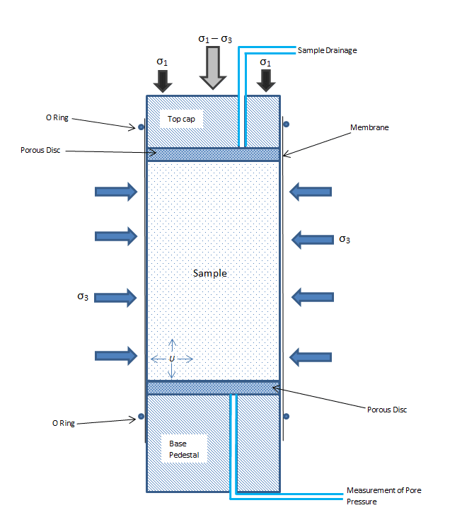
Yes, it is solid. I started to think that maybe I should change the way I implement this triaxial test. To explain, in a real experiment, they put a sample (usually soil) in a case and using the pressure of water encompassing the case they try to impose a hydrostatic pressure. Afterwards, maintaining the pressure produced by water, they put a uniaxial load on the sample to make the pressure in one direction increase. (I attached a photo illustrating the procedure). Now, I have the sample that is under a hydrostatic pressure and I want to impose an extra uniaxial pressure in one direction. (with periodic boundary condition) Do you have any idea about how to perform this test more correctly?
What I have done for similar systems is to use fix add_force on the atoms at the border of the cell to impose a well defined pressure in a direction of the material. I think that this is cleaner than using fix npt.
To do so, you have to create a block of solid in vacuum instead of an “infinite” block as I suppose you have right now. Then place the “border atom” in groups, and apply a “fix add_force” to those atoms.
Well, since I cannot ignore the periodic boundary condition, I think it’s not possible for me to define a loading on the boundary. What do you think about keeping the “fix npt” as the constant hydrostatic pressure produced by water in the x and y directions and adding a force to all the atoms in the z direction? Is the fix add_force capable of this?
If you are adding the same force to all atoms, you will just translate the system.
For how many steps do you actually run the MD with fix npt?
If my math is correct, then not for very many. That is likely the problem.
Also your values for Tdamp and Pdamp appear very short.
You need to give your system time to react. If the simulation lasts only a few femtoseconds, then this will not happen.
I was trying to impose the loading at the rate of 0.0025 GPa/fs, which is even 4 times slower than what is recommended in the literature, but I will definitely try slower rates as you suggest.
Also, I have a very important question about Tdamp and Pdamp and I would be more than happy if you share with me your experience. For this simulation, what Tdamp and Pdamp you suggest and why? Do you suggest using different Pdamp for different directions?
With a 2.5 GPa change, that would correspond to a simulation time of only 1ps. That is very short.
At any rate, you need to first equilibrate your system to the starting conditions and that can easily take 10s if not 100s of picoseconds. For a solid probably at the lower end of the spectrum, though.
Then you can run the pressure ramp and you will need to hold the pressure at that value for some additional time since you will reach the desired target pressure only at the last step of the ramp, but you need to give your system time to react to it. How fast the system reacts is also determined by the choice of Pdamp.
The fix npt documentation recommends to try using a Tdamp of 100 timesteps (= 20fs) and Pdamp
of 1000 timesteps (=200fs). For a solid the Pdamp value may need to be larger if the simulation otherwise becomes unstable.
I tried what you suggested and it worked! But this gives rise to another question:
The initial model, which was being used in the triaxial test, was completely relaxed at a prior stage and its restart file was created to be used in the triaxial test code. Why it required us to perform yet another relaxation after using the relaxed system from the restart file? What’s the logic behind this?
Relaxed or equilibrated to the starting conditions of this simulation?
Relaxed in the context of MD simulations usually refers to the result of a geometry optimization through a minimization algorithm (often also including relaxation of the box dimensions), while equilibration refers to running a system for a sufficient amount of time at the desired conditions with a thermostat (and optionally a barostat) until the system is in equilibrium with the desired thermodynamic conditions.
I was describing the most general situation and cannot assume that the system was already properly equilibrated. I didn’t recall any mention of a previous equilibration. At any rate, some additional equilibration time never hurts, but too little equilibration causes problems and taints the results.