Hello everyone
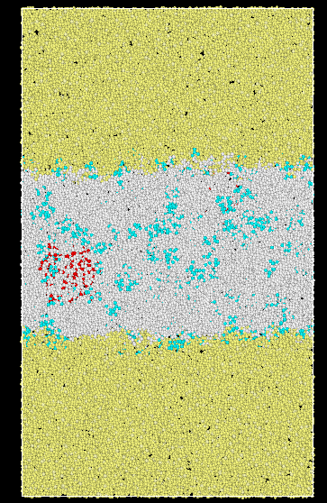
I want to the PMF of the solute along the z-direction (Below is my system image. Yellow particles are oil, white particles are water, and green particles are solute).
The following figure shows some parameter Settings in the literature when calculating the PMF of the solute.

I have the following questions:
-
How to control the calculation that the solute PMF is going in the Z direction
-
How to control the sampling area of the PMF calculation to be 6nm
-
How to control the placement of three probe molecules at 2 nm intervals along the Z axis at three different locations
Below is the script file for my PMF calculation
group pull1 id 10
group pull2 id 20
###loop for umbrella windows
label loop
variable dr0 index 20
fix smd umbrella / equilibrium
k=800kj/(molnm^2)=1.912kcal/(molA^2)
fix 40 pull1 smd cvel 1.912 0.0 couple pull2 NULL NULL auto ${dr0}
run 1000
output data
variable tt equal dt*step
variable dr equal f_40[6]
fix 50 pull1 print 10 “{tt} {dr}” file umbrella.{dr0}.pmf screen no
dump {dr0} all custom 100 smd.${dr0}.lammpstrj id type x y z
run 5000
If the question is about your LAMMPS input, you should be a bit more specific and ask something that isn’t already covered in the documentation.
Part of the issue is that the paper you are quoting may not be the most clear in terms of methodology. It seems as if they re-used the same simulation system and put three copies of the same molecule to multiply their sampling efficiency by a factor of 3, and then they say that they have validated their results against PMFs with larger intervals. This seems to have saved some computer time, but wasted the researcher’s time by making it more complicated than it needs to be.’
I would suggest fine-tuning your LAMMPS script on a tiny system (cheap to simulate) and then try the full-size computation. Since you are using a very simple collective variable and it is a liquid-liquid interface without any complex structure, you could equilibrate different structures for each umbrella and run them independently, instead of initializing the windows consecutively. If you find that the windows don’t overlap, you can always add extra windows in between to get a continuous PMF.
Giacomo
Thank you very much for your answer, Giacomo
I have one more question,since I have multiple solute molecules in my system, do I only need to select two of them as probe molecules when Calculating solute PMF? Then set it through “group pull1 molecule 1 , group pull2 molecule 2”
Sorry to bother you again.Thank you very much
zz
If you have multiple solute molecules in your system, then you have to ensure that (1) they represent the correct concentration that you are trying to model and (2) interactions between solute molecules are also sampled correctly. There is no easy way to do that. If you are starting from the basics, you should start with one solute molecule.
Giacomo
Thank you very much for your patient answer, Giacomo