Hi,
I want to model an infinite slab under NPT thermalization. I need to apply the periodic boundary conditions (PBC) only in 2 directions (X and Y) and free BC (Z direction). I do not want to use shrink-wrapped in Z direction Because under NPT, shrink-wrapped BC cannot be used. Is there anyway in LAMMPS I can do this?
Also, I am wondering if I want to apply PBC partially along the thickness (t) of the slab, what should I do? If we assume that t=t1+t2, I only need to apply PBC on t1.
I would be very thankful if you can help me.
Hossein
Hi,
I want to model an infinite slab under NPT thermalization. I need to apply
the periodic boundary conditions (PBC) only in 2 directions (X and Y) and
free BC (Z direction). I do not want to use shrink-wrapped in Z direction
Because under NPT, shrink-wrapped BC cannot be used. Is there anyway in
LAMMPS I can do this?
you can use periodic boundaries in 3 dimensions and either use a poisson
solver to compensate the inter-slab long-range interactions or just make
certain that the distance between the top of the slab to and the bottom of
its periodic image is sufficiently large to exceed the cutoff of your
potential.
Also, I am wondering if I want to apply PBC partially along the thickness
(t) of the slab, what should I do? If we assume that t=t1+t2, I only need
to apply PBC on t1.
there is not such thing as a partial periodicity.
axel.
Thanks for your quick reply. I know the trick you mentioned that making
the simulation box larger in the Z direction to avoid interactions over the
boundary. I have used this for some problems I had before.
But now the main issue is that if we assume that we have a nanowire (or
pillar) on top of the slab. If we use a simulation box which is periodic in
all directions. Also, we use that trick and increase the size of box in the
Z direction. But this pillar is vibrating significantly and it touches the
PBC in X and Y directions which is not appropriate for us.
sorry, but i don't see the connection between one and the other. it sounds
more to me that you have too small a box in x and y, and also the
vibrations you mention sound more like a problem with the system setup than
an issue from using a slab setup with ppp boundaries.
please keep in mind that i mentioned that the extent has to be large
enough.
that being said, from what you say, i am wondering whether you need to use
a variable cell calculation altogether? can't you just set up and
equilibrate your slab on its own. and then just run with a fixed volume
based on the equilibrated average box dimensions in x- and y- and then
merge it with your "pillar", equilibrate that by itself and do your
production calculation.
it is always good to keep things simple and build complex systems in
increments.
axel.
Dear Axel,
I think I did not explain clearly.

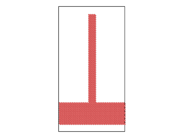
The pillared system is one system and they should be studied together. So they cannot be simulated separately. For better understanding of the problem, I attached a figure shows the system. The simulation box has PPP boundary conditions. And when pillars resonate they touch the simulation box walls in X and Y directions. Also, it can be seen that I considered a gap in the Z direction for both bottom and top. So it implies free surface BC.
Please let me know about your comments.
Best
Dear Axel,
I think I did not explain clearly.
The pillared system is one system and they should be studied together. So
they cannot be simulated separately. For better understanding of the
problem, I
i didn't say to simulate separately, but you most certainly can set up and
prepare that system exactly like i have described.
attached a figure shows the system. The simulation box has PPP boundary
conditions. And when pillars resonate they touch the simulation box walls
in X and Y directions. Also, it can be
there are no walls in periodic boundaries.
seen that I considered a gap in the Z direction for both bottom and top.
So it implies free surface BC.
Please let me know about your comments.
everything i mentioned previously still holds.
Dear Alex,
Thanks for your explanations. I thought about the method (variable cell calculation) you mentioned and searched for that. But I am not quite convinced how it can be applied to my system. It is much appreciated if you can give me some hints or introducing some good references explaining it clearly?
Thanks so much!