Applying Constant Shear Stress to Dislocation Using Lammps

Dear Members of the LAMMPS Community,

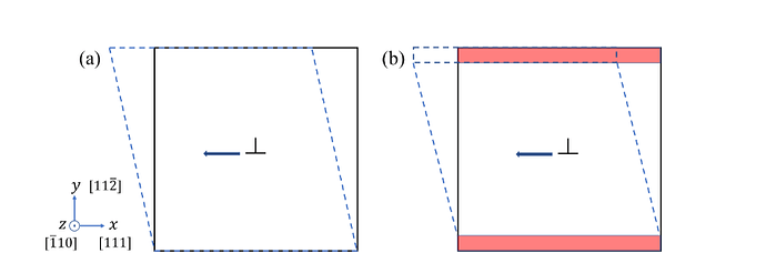
I find myself facing a challenging issue and would greatly appreciate any assistance with my current LAMMPS simulation. My research involves investigating the motion of an edge dislocation under a constant shear stress. The simulation cell I am utilizing closely resembles the one depicted in the figure below:

The dimensions of this cell are as follows: lx = 450A, ly = 320A, and lz = 100A.

To create the edge dislocation, I employed ATOMSK and subsequently performed an energy minimization using the conjugate gradient (CG) method. Afterward, I conducted an NVT (constant number of particles, volume, and temperature) simulation to equilibrate the structure at 0.01K.

Finally, I applied a constant stress at top red layer using the fix aveforce command and continued the simulation with fix nvt for a duration of 120ps.

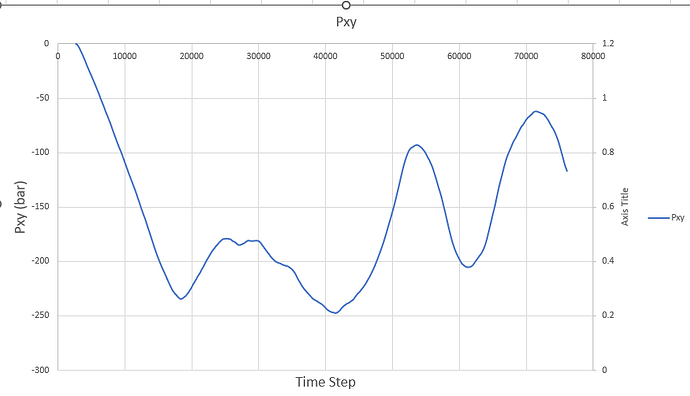
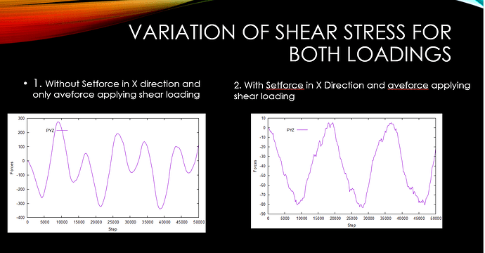
I had anticipated that the shear stress (pxy) obtained from the simulation would match the applied stress. However, contrary to my expectations, the shear stress exhibits variations with each timestep, as illustrated in the figure below:

I find myself perplexed and unable to pinpoint the source of this discrepancy. Any insights or guidance you can provide would be immensely helpful in resolving this issue. One question I have is whether I should apply shear stress under the fix npt ensemble.
I have attached a snippet of my code that is used to apply stress below:

# Calculation of Forces in Upper and Lower Group of Atoms
variable natoms_upgrp equal count(upgrp)
variable natoms_logrp equal count(logrp)
variable stress equal 18 # MPa
variable lx0 equal lx # A
variable lz0 equal lz # A
variable force equal ${stress}*${lx0}*${lz0}*1e-14 # N
variable fx_up equal (${force}*1e9)/(${natoms_upgrp}*1.602)
variable fx_lo equal (${force}*1e9)/(${natoms_logrp}*1.602)
# 1eV/A = 1.602e-19/1e-10 = 1.602e-9N
# 1N = 1e9/1.602
print ${fx_up}
print ${fx_lo}
# Add force & Set force  - Apply Forces on top surface
fix f4 upgrp aveforce ${fx_up} 0. 0.
fix f2 upgrp setforce NULL 0.0 NULL
fix f3 logrp setforce 0.0 0.0 NULL 
fix f6 upgrp rigid group 1 upgrp
fix f1 mobile nve 
fix f7 mobile temp/rescale 10 ${temperature} ${temperature} 0.03 1
# fix f1 mobile nvt temp ${temperature} ${temperature} ${tdamp}

# Variables Defination
variable f4ax atom f_f4[1]


# Outputs
dump d5 all custom 500 A5_result_s5 id x y z c_stress[*] c_cysm v_f4ax v_disid 
dump d6 all custom 500 B6_result_s6 id xu yu zu c_stress[*] c_cysm v_f4ax v_disid 
fix fout2 all ave/time 1 250 300  f_f4[1] file forces.txt


run 120000


Some pretty straightforward questions:

  1. Have you visualised your trajectory (that is, seen how the particles actually move over time in a program like VMD?)
  2. How do you know your system can return a steady response to the stress in only 120 picoseconds?
  3. What units are you using? Are you sure your conversions are correct?
  4. If a dislocation is being sheared then shouldn’t the system’s response to shear stress be variable and uncertain?
  5. Under shear, different parts of the simulation box will develop relative motion. Are you sure fix nvt isn’t picking this up as thermal energy and erroneously damping it?

Hi Stree
Thankyou for the reply.
Here are the details with respect to my simulation.
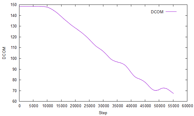
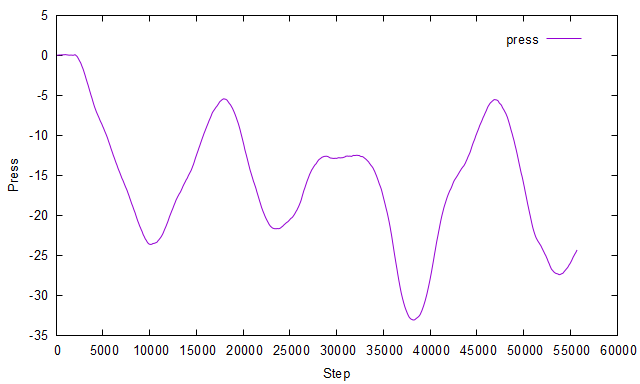
Yes I have visualized the dislocation trajectory using ovito. The dislocation moves under the shear stress. The variation of dislocation centre of mass and shear stress with respect to time steps is shown in below graphs:
Dislocation Centre of Mass
image
Shear Stress Pxy

image

The dislocation moves under the shear stress. These graphs are obtained when I apply +18MPa to top surface and -18MPa to bottom surface.
Using molecular statics I have also calculated the Peierls Stress - i.e. stress required to initiate dislocation motion at 0K it comes around 23MPa. As I am applying only 18MPa I am expecting that dislocation should move under stress as for dynamics case My temperature is only 1K.
I have ensured that I am modelling using consistent units.
My query with respect to above simulations are:

  1. Shouldn’t the lammps calculated pxy should be equal to applied shear stress (i.e. 18MPa in this case)
  2. As the applied stress is less than Peierls stress (accuracy of Peierls stress I have verified from literature), then the dislocation shouldn’t be moving under 18MPa stress
  3. Why there is variation in shear stress with respect to time

I would be very grateful if you help in understanding these details.

You problem seems to be predominantly one of trying to apply knowledge and logic that are applicable to macroscopic systems to atomic scale simulations. That will not work. You have to go through statistical thermodynamics to relate atom scale data to macroscopic observables.

Secondly, as already alluded to by @srtee, neither of the thermostat options are applicable to the constant shear simulation setup. You must take into account the bias from the shearing or you have to make the shearing speed so small that those differences won’t matter (and thus your simulation must be must longer). Since you are simulating a solid, that option seems to be most promising. Furthermore, you should never use fix temp/rescale in any kind of production simulation. If I am not mistaken, LAMMPS offers the option to follow the SLLOD equations of motion and the UEF package implements a generalization of that.

Third, as part of the differences between macroscopic and atomic scale simulation, you have to take into account fluctuations. Pressure/stress is having particularly large fluctuations since condensed media is not very compressible (especially solids). Thus you can only obtain meaningful results with averaging over time, assuming that your system is in a steady state. Alternately, you can also (significantly) increase your system size to reduce fluctuations.

It certainly looks like the average value is about 18 MPa, which should give you some confidence that you’re on the right track.

No idea. I don’t do solid MD. But if you search the forum for the keyword “Peierls” you will find earlier posts that have discussed your topic of research. Those should give you some idea.

Because you are simulating a system that is physically very small, millions of times smaller than a grain of sand. The bigger a system is (in general) the smaller its relative fluctuations are. The opposite is also true.

1 Like

Thankyou very much @srtee for the help and guidance.

Hi, Vikram_Roy, I have also encountered a similar problem, could you please help me.

Q1: According to the LAMMPS manual, “addforce” adds additional force to the specified atom. Therefore, according to my script, after the loop ends, the shear stress loaded on the “upper” atoms should be “(1+2+3+4)500=5000 MPa” . However, when I finished running, I found that the shear stress loaded on the “upper” atoms was only “4500=2000 MPa” .

Q2: The edge dislocation is immobile even if the shear stress is 2000 MPa in bcc Fe, which is inconsistent with the fact.

I wonder if you could give me some advice. Looking forward to your reply.

Thank you very much!

The following is the LAMMPS script:

#constant stress-shear (edge dislocation) for the bcc fe at 300 K

------------------------ INITIALIZATION ----------------------

units metal

dimension 3

boundary p s p

atom_style atomic

----------------------- ATOM DEFINITION ----------------------

timestep 0.001

read_data fe-edge_c-x50y30z10.lmp

----------------------- FORCE FIELDS --------------------------

pair_style meam/c

pair_coeff * * library.meam Fe H FeH.meam Fe H #No H atom

variable Ylo equal ylo

variable Yhi equal yhi

variable Yl equal ${Ylo}+11.17765

variable Yu equal ${Yhi}-11.17765

region lower block INF INF INF ${Yl} INF INF units box

region upper block INF INF ${Yu} INF INF INF units box

group lower region lower

group upper region upper

group boundary union lower upper

group mobile subtract all boundary

compute new3d mobile temp

thermo 1000

thermo_style custom step temp pe ke epair etotal press vol pxx pyy pzz pyz lx ly lz

thermo_modify temp new3d

minimize

dump min all custom 100 dump.min.* id type x y z

minimize 1e-15 1e-15 10000 100000

undump min

reset_timestep 0

neighbor 0.5 bin

neigh_modify every 2 delay 10 check yes

npt equilibrate

dump relax all custom 20000 dump.relax.* id type x y z

velocity mobile create 300.0 123456 temp new3d # dist gaussian

fix 1 all npt temp 300 300 0.1 x 0 0 1 z 0 0 1 drag 1

fix_modify 1 temp new3d

fix 2 boundary setforce 0.0 0.0 0.0

run 100000

unfix 1

unfix 2

undump relax

reset_timestep 0

apply Forces on Upper and Lower Group of Atoms

variable EvStress equal 500 #MPa

variable NatomsUp equal count(upper)

variable NatomsLow equal count(lower)

variable acs loop 1 4

label start_loop

variable appliedStress equal {acs}*{EvStress} # in MPa; units eV/A, “v_appliedStress/160217.662089”

variable lz equal “lz”

variable Lz0 equal v_lz

variable lx equal “lx”

variable Lx0 equal v_lx

variable area equal {Lx0}*{Lz0}

variable forcePerAtomUp equal {appliedStress}/160217.662089*{area}/${NatomsUp}

variable forcePerAtomLow equal -1.0*{appliedStress}/160217.662089*{area}/${NatomsLow}

print "--------------------acs={acs} applied stress={acs}*{EvStress}={appliedStress}-------------------- "

print “--------------------lx={Lx0}, lz={Lz0}, area={area}, NatomsUp={NatomsUp}, NatomsLow=${NatomsLow}--------------------”

print “--------------------forcePerAtomUp={appliedStress}/160217.662089*{area}/{NatomsUp}={forcePerAtomUp}--------------------”

print “--------------------forcePerAtomLow=-1.0*{appliedStress}/160217.662089*{area}/{NatomsLow}={forcePerAtomLow}}--------------------”

fix shearUp upper addforce ${forcePerAtomUp} 0.0 0.0

fix shearLow lower addforce ${forcePerAtomLow} 0.0 0.0

fix_modify shearUp energy yes

fix_modify shearLow energy yes

fix 1 mobile nvt temp 300 300 0.1

fix_modify 1 temp new3d

thermo_modify temp new3d

dump applystress all custom 1000 dump.cs_shear_applystress_{acs}-{EvStress}_${appliedStress}MPa.* id type x y z fx fy fz

run 50000

unfix 1

unfix shearUp

unfix shearLow

undump applystress

write_restart cs_shear_applystress_{acs}-{EvStress}_${appliedStress}MPa.restart

reset_timestep 0

next acs

jump SELF start_loop

#After the loop, the {appliedStress}={acs}${EvStress}=4500=2000 MPa

#Keeping the syestem at a ${appliedStress}=2000 MPa for 100 ps, and observing the slip of dislocations.

print "--------------------applied stress=${appliedStress}-------------------- "

restart 100000 cs_shear_${appliedStress}MPa.restart

fix shearUp upper addforce ${forcePerAtomUp} 0.0 0.0

fix shearLow lower addforce ${forcePerAtomLow} 0.0 0.0

fix_modify shearUp energy yes

fix_modify shearLow energy yes

fix 1 mobile nvt temp 300 300 0.1

fix_modify 1 temp new3d

thermo_modify temp new3d

dump shear all custom 1000 dump.cs_shear_{acs}-{EvStress}_${appliedStress}MPa.* id type x y z fx fy fz

run 200000

unfix 1

unfix shearUp

unfix shearLow

undump shear

Hi,

Tryout with these set of codes. They worked for my job

# LAMMPS Input file for Energy Minimization of Atomic Structure

# Echo both to terminal and log file
clear
echo both

# Delete Old Files & Create Atomic Structure using Atomsk
shell "if exist *_result_* (del *_result_*)"
shell "if exist result_* (del result_*)"
shell "if exist temp.txt (del temp.txt)"
shell "if exist forces.txt (del forces.txt)"
shell "if exist discom.txt (del discom.txt)"
# shell deloldfiles.bat
# shell createdis.bat

# Variables Declaration
# File Name Containg input atomic structure
variable filename string Fe_Screw_cell.lmp
variable enertol equal 1e-15
variable fortol equal 1e-15
variable eiter equal 10000
variable fiter equal 10000
variable burgerv equal 2.560
variable delx1 equal v_burgerv/5
variable tstep equal 0.001
variable temperature equal 1
variable tdamp equal ${tstep}*100
variable pdamp equal ${tstep}*10

# Initialization
units metal
dimension 3
atom_style atomic 
boundary p s p

# Read Atomic File
read_data ${filename}
change_box all triclinic


# Define Regions and Groups
region upper block INF INF 135 INF INF INF
region lower block INF INF INF 15 INF INF
group upgrp region upper
group logrp region lower
group fixed union upgrp logrp
group mobile subtract all fixed
variable gid atom gmask(mobile)+2*gmask(fixed)

# Calculation of Forces in Upper and Lower Group of Atoms
variable natoms_upgrp equal count(upgrp)
variable natoms_logrp equal count(logrp)
variable stress equal 5 # MPa
variable lx0 equal lx # A
variable lz0 equal lz # A

# 1eV/A = 1.602e-19/1e-10 = 1.602e-9N
# 1N = 1e9/1.602


# Potential Settings
pair_style eam/fs
pair_coeff * * Fe.eam Fe

# pair_style	eam
# pair_coeff	* * Cu_u3.eam

# Computes
compute cysm mobile centro/atom bcc
compute stress mobile stress/atom NULL

# Outputs
thermo 150
thermo_style custom step temp etotal press pxx pyy pzz pxy pyz pxz
dump d1 all custom 50 results/A1_result_s1 id x y z c_stress[*] c_cysm v_gid
dump d2 all custom 50 results/B2_result_s2 id xs ys zs c_stress[*] c_cysm v_gid

# Energy Minimization
min_style cg
minimize ${enertol} ${fortol} ${fiter} ${eiter}
# run 10

undump d1
undump d2


# Check Equilibriation
fix fout2 all ave/time 1 8 10 c_thermo_temp file temp.txt
# Outputs
dump d3 all custom 50 results/A3_result_s3 id x y z c_stress[*] c_cysm 
dump d4 all custom 50 results/B4_result_s4 id xs ys zs c_stress[*] c_cysm


#thermalization
timestep ${tstep}
velocity mobile create ${temperature} 12354 units box
velocity mobile zero linear
velocity mobile zero angular
velocity upgrp set 0 0 0 units box
velocity logrp set 0 0 0 units box
fix f1 mobile nvt temp ${temperature} ${temperature} ${tdamp}
# fix f1 mobile nve 
# boundary condition
fix f2 logrp setforce 0.0 0.0 0.0
fix f3 upgrp setforce 0.0 0.0 0.0
run 20

undump d3
undump d4
unfix f1
unfix f2
unfix f3
unfix fout2


variable n equal 0


reset_timestep 0
# Create Dynamic Group of Dislocation
variable dis atom "c_cysm>0.5"
group disloc variable dis
group disloc1 dynamic all var dis every 1
variable disid atom gmask(disloc1)
compute disid_com disloc1 com
fix fix_dcom disloc1 ave/time 1 20 25 c_disid_com[1] file dcom.txt


# Outputs
dump d5 all custom 250 results/A5_result_s5 id x y z c_stress[*] c_cysm  v_disid
dump d6 all custom 250 results/B6_result_s6 id xu yu zu c_stress[*] c_cysm  v_disid 
# fix fout2 all ave/time 1 50 60  v_f4ax file forces.txt

# label loop1

fix f1 all nve
run 0
unfix f1
variable temp equal c_disid_com[1]
variable dcom_initial equal ${temp}

variable temp equal ${n}
variable n equal ${temp}+1

variable velocity_z equal 0.0002
variable clo equal 15
variable chi equal 135

# Calculation of Forces in Upper and Lower Group of Atoms
variable natoms_upgrp equal count(upgrp)
variable natoms_logrp equal count(logrp)
variable stress equal 500 # MPa
variable lx0 equal lx # A
variable lz0 equal lz # A
variable AppliedStress equal v_stress*v_n
print ${AppliedStress}
variable force equal ${AppliedStress}*${lx0}*${lz0}*1e-14 # N
variable fx_up equal (${force}*1e9)/(${natoms_upgrp}*1.602)
variable fx_lo equal (${force}*1e9)/(${natoms_logrp}*1.602)
print ${fx_up}
print ${fx_lo}

fix f2 upgrp setforce 0.0 0.0 NULL
fix f3 logrp setforce 0.0 0.0 0.0 

fix f4 upgrp aveforce 0. 0. ${fx_up}

fix f6 fixed rigid group 2 upgrp logrp
# fix f1 mobile nve 
fix 5 mobile nvt temp 1 1 0.1 drag 1
# velocity all ramp vz 0 ${velocity_z}   y ${clo} ${chi} sum yes units box  
# Variables Defination
variable f4ax atom f_f4[1]
variable f4ax1 equal ${fx_up}*${natoms_upgrp}/f_f4[1]
variable pyz1 equal pyz
fix fout2 all ave/time 1 50 60  f_f4[1] v_f4ax1 v_pyz1 file forces_${n}.txt

print ${dcom_initial}


run 30000


# unfix fout2

# variable temp1 equal c_disid_com[1]
# variable dcom_final equal ${temp1}
# variable dcom_diff equal ${dcom_final}-${dcom_initial} 
# if "(${dcom_diff} > 0.25) || (${dcom_diff} < -0.25) " then "jump SELF loop2" else "jump SELF loop1"

# label loop2

# run 0
# variable temp1 equal c_disid_com[1]
# variable dcom_intial1 equal ${temp1}

# fix fout3 all ave/time 1 50 60  f_f4[1] v_f4ax1 v_pxy1 file forces_${n}_2.txt

# fix f4 upgrp aveforce ${fx_up} 0. 0. # Also Check with AddForce
# fix f2 upgrp setforce NULL 0.0 NULL
# fix f3 logrp setforce 0.0 0.0 NULL 
# fix f6 upgrp rigid group 1 upgrp
# fix f1 mobile nve 

# run 200000
# unfix fout3
# variable temp1 equal c_disid_com[1]
# variable dcom_final1 equal ${temp1}
# variable dcom_diff1 equal ${dcom_final1}-${dcom_intial1}
# if "(${dcom_diff1} > 3.0) || (${dcom_diff1} < -3.0) " then quit else "jump SELF loop1"


# undump d5
# undump d6


I will try it. Thank you very much!

Hello Lin!
I’m currently facing a similar issue. When applying shear stress to a dislocation, the threshold stress I obtained is always higher than reported in other studies. My script is quite similar to yours.Have you resolved this issue now?
Looking forward to your reply!

Sorry to disturb you. I do not understand what is your shear direction. Your first figure shows it is x
direction. However, your last code shows it is z direction. Look forward to your reply.

Dear owoo:
I have encountered the same problem as you. The result I calculated is much larger than the results in other studies.
I have tried to run the script provided by Vikram_Roy. However, the dislocation shows no sliding.
The script I used is shown as follows. Have you encounted those problem and resolved them? Look forward to your reply.

change_box          all boundary p p s

reset_timestep      0
timestep            0.001
variable            tmpx equal lx
variable            L0x equal ${tmpx}

variable            deltaL  equal  (lx-${L0x})
variable            sxz equal "-pxz/10"          # calculate shear stress
variable            strain equal v_deltaL/lx        # calculate shear strain

variable			dyna_step equal 15000

# deformation starts!
fix				    1 mobile nve
fix                 2 mobile temp/rescale 10 ${Temp} ${Temp} 10.0 1.0
fix_modify          2 temp new2d

fix                3 upper move linear -0.2 0.0 0.0 units box
velocity           mobile ramp vx 0 -0.2 z ${lower_layer_limit} ${upper_layer_limit} sum yes units box
run                ${dyna_step}