AtC: Regarding definition of SiO2 unit cell for thermal simulation

Dear LAMMPS users,

I am trying to simulate thermal flux through SiO2 crystal using AtC package. Below are the details of the problem I am facing:

Version of LAMMPS used : 1Feb14
Question regarding package : Atc
Type of phenomenon being simulated : Thermal flux in SiO2
Short description of problem : Simulation is not completed due to unknown error
Detailed description of problem:
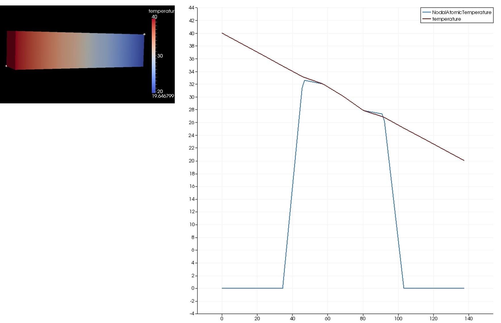
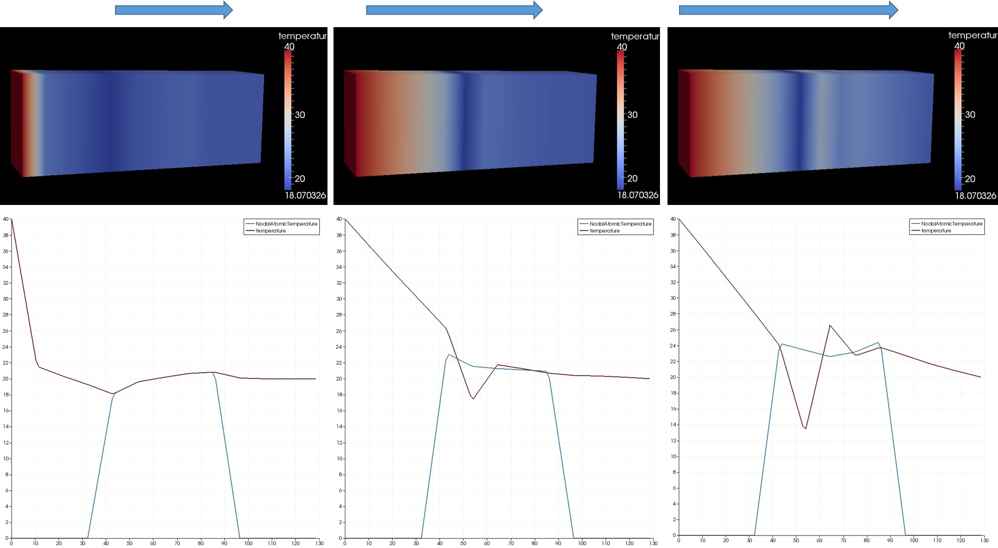
In order to simulate the thermal flux in SiO2 (alpha quartz), I modified the input file “in.bar1d_flux” in the example folder “thermo” under the “atc” examples.
Below is my modified input file where I am defining the SiO2 unit cell using the “lattice” command. My simulation gets terminated after 30 timesteps.
When I ran the simulation using the “-echo screen” option, the following line gets printed in the log file:
“DiagonalMatrix::inv(): (0,0)=0”.

I am not sure what this means.

Questions:

  1. Could you please suggest a way to specify the Silica unit cell that is acceptable for the AtC package?
  2. Why do I get the following warning - “ATC: WARNING: Cannot get number of atoms per cell from lattice” ?
  3. Is the warning the cause for the error or can I ignore it since its just a warning?

#Start of input script------

units metal
newton on
atom_style charge
dimension 3
boundary p p p

lattice custom 5.4054 origin 0.25 0.25 0.25 &
a1 0.90950000 0.00000000 .00000000 &
a2 0.00000000 0.78760000 .00000000 &
a3 .00000000 .00000000 1.00000000 &
basis 0.46990000 0.00000000 0.66666667 &
basis 0.00000000 0.46990000 0.33333333 &
basis 0.53010000 0.53010000 0.00000000 &
basis 0.41410000 0.26810000 0.78540000 &
basis 0.73190000 0.14600000 0.45206667 &
basis 0.85390000 0.58589999 0.11873333 &
basis 0.26810000 0.41410000 0.21460000 &
basis 0.58589999 0.85399999 0.88127777 &
basis 0.14600000 0.73190000 0.54793333

#region box prism 0 10 0 10 0 10 -0.4547 0 0
region simRegion block -12 12 -3 3 -3 3
region mdRegion block -5 5 -3 3 -3 3

create_box 2 mdRegion
create_atoms 1 region mdRegion &
basis 1 1 &
basis 2 1 &
basis 3 1 &
basis 4 2 &
basis 5 2 &
basis 6 2 &
basis 7 2 &
basis 8 2 &
basis 9 2

mass 1 28.09
mass 2 16.0

region mdInternal block -4 4 -3 3 -3 3
group internal region mdInternal
group ghost subtract all internal

pair_style lj/cut 2.5
pair_coeff * * 1.0 1.0 2.5
pair_coeff 1 2 1.0 2.0 3.5
pair_coeff 2 2 1.0 3.0 4.0
neighbor 5. bin
neigh_modify every 10 delay 0 check no

minimize 1.0e-4 1.0e-6 100 1000

#dump D1 all atom 100 dump.minbar1d

fix AtC internal atc thermal SiO2_thermal.mat
fix_modify AtC boundary ghost
fix_modify AtC time_integration fractional_step

ID part keywords nx ny nz region

fix_modify AtC mesh create 12 6 6 simRegion p p p
fix_modify AtC mesh create_faceset ibndy box -4.0 4.0 -INF INF -INF INF in
fix_modify AtC mesh create_faceset obndy box -4.0 4.0 -INF INF -INF INF outward

fix a temperature

fix_modify AtC fix temperature all 20.

turn on thermostat

fix_modify AtC control thermal rescale 10

dump D2 all atom 10 dump.bar1d
timestep 5
thermo 10
run 400

#end of input script------

Thank you,
Stephen Thomas.

I don’t know too much about the AtC package, but I am certain your alpha-quartz unitcell is incorrect. An alpha quartz unitcell with 9 atoms is hexagonal (or trigonal), while yours is tetragonal.

Ray

Dear Ray Shan,

Thanks for pointing it out. I modified the lattice to hexagonal. Below is my new lattice and basis:

lattice custom 5.4054 origin 0.25 0.25 0.25 &
a1 0.9094609228 0.0000000000 0.0000000000 &
a2 -0.4547304614 0.7876162629 0.0000000000 &
a3 0.0000000000 0.0000000000 1.0000000000 &
basis 0.469700009 0.000000000 0.000000000 &
basis 0.000000000 0.469700009 0.666666687 &
basis 0.530300021 0.530300021 0.333333343 &
basis 0.413500011 0.266900003 0.119099997 &
basis 0.266900003 0.413500011 0.547566652 &
basis 0.733099997 0.146600008 0.785766661 &
basis 0.586499989 0.853399992 0.214233339 &
basis 0.853399992 0.586499989 0.452433318 &
basis 0.146600008 0.733099997 0.880900025

However, I still get the same error with the AtC fix.

Thank you,
Stephen Thomas.

Hi Stephen,

The AtC fix uses the unit cell to estimate a per-atom equivalent volume. Since you are using a custom lattice it can’t access that information. I suggest you try manually specifying the atomic weight:

http://lammps.sandia.gov/doc/USER/atc/man_atom_weight.html

Jeremy

Hi Stephen,

Your alpha-quartz is still incorrect. Try the following:

lattice custom 1.0 a1 4.8560000 -2.4280000 0.00000000 &

a2 0.0000000 4.8560000 0.00000000 &

a3 0.00000000 0.00000000 5.31600000 &

basis 0.46970 0.00000 0.00000 &

basis 0.00000 0.46970 0.66667 &

basis 0.53030 0.53030 0.33333 &

basis 0.41330 0.26720 0.11880 &

basis 0.73280 0.14610 0.78547 &

basis 0.85390 0.58670 0.45213 &

basis 0.26720 0.41330 0.54787 &

basis 0.14610 0.73280 0.88120 &

basis 0.58670 0.85390 0.21453

Dear Dr. Templeton,

Since my material is alpha quartz, it has two atom types. I am trying to figure out how I can assign atomic weights of multiple atom types using the “atom_weight” command. I made two guesses for doing this:

  1. Assign a group representing a enclosing a single atom of each type and assign the respective atomic weight.

  2. Use the AtomicVolumeFile to provide a list of all the atom type and atom weight in the MD region.

Please advice me on how to handle this.

For option 2, I could not find a sample file for understanding the syntax. Could you please send me one?

Thank you,

Stephen Thomas.

Dear Dr. Templeton,

Another question I had was regarding the .mat file specifying the conductivity. In the example file “in.bar1d_flux”, “Ar_thermal.mat” is used. Could you clarify the following about the contents about this file?

material Ar real
heat_flux linear
conductivity .00000000168
end
end

material Ar2 real
heat_flux linear
conductivity .00000000316
end
end

material vacuum real
end

Q1) Why is there two Ar material descriptions “Ar” and “Ar2”?

Q2) In section 7 of Dr. Wagner’s paper, it is mentioned that thermal conductivity of 0.5 W/(mK) is used. How does that value relate to the values for conductivity used above?

Q3) For the SiO4 simulation I am attempting, am I correct to assume that I can just specify one material description about SiO4 since this is finite element conductivity value and does not involve individual atom types?

Thank you,

Stephen Thomas.

Hi Stephen, answers in line below.

Dear Dr. Templeton,

Another question I had was regarding the .mat file specifying the conductivity. In the example file “in.bar1d_flux”, “Ar_thermal.mat” is used. Could you clarify the following about the contents about this file?

material Ar real
heat_flux linear
conductivity .00000000168
end
end

material Ar2 real
heat_flux linear
conductivity .00000000316
end
end

material vacuum real
end

Q1) Why is there two Ar material descriptions “Ar” and “Ar2”?

Atc supports multiple materials in a single file as well as in the finite element piece. This file is merely to demonstrate that capability. The Ar2 is a dummy material.

Q2) In section 7 of Dr. Wagner’s paper, it is mentioned that thermal conductivity of 0.5 W/(mK) is used. How does that value relate to the values for conductivity used above?

In our papers we report units in SI, but those provided to the code must be consistent with LAMMPS’ time/length/mass units.

Q3) For the SiO4 simulation I am attempting, am I correct to assume that I can just specify one material description about SiO4 since this is finite element conductivity value and does not involve individual atom types?

That would be my guess, but I am not the expert in that case… you are. Formulate what you think is an appropriate mathematical model independent of the particular code and then see if you can translate that model into LAMMPS/ATC or whatever other code makes the most sense.

Dear Dr. Templeton,

As explained in the previous mails in this chain, I am trying to recreate the 1D heat flux (Argon) example using SiO2 (alpha quartz). This simulation uses the coupling method in AtC. The temperature is intially raised to 20 K through out the domain and then the opposite sides along X axis is maintained at 40 K (left side) and 20 K (right side). The expected outcome is a “steady state” in the heat flux as shown below (for Argon). The plot shows “temperature” and “Nodal Atomic Temperature”:
heatflux_Argin.jpg

But, when I use SiO2, there seems to be an error in the simulation which causes the FE temperature to go to unnatural values (<0K) when I let the simulation run for a long time. The heat flux does not achieve “steady state” (linearly decreasing between boundaries as seen in the case of the Argon example). Bellow are some of the screen shots to illustrate the condition. The images is arranged in increasing order of time step from left to right. The plot shows “temperature” and “Nodal Atomic Temperature”. Initially, the “temperature” plot coincides with the “Nodal Atomic Temperature” plot. But as the simulation proceeds, the two spikes (one downward and the other downward) develop and reach really low values (-89K) and really high values (212K)
AlphaQuartz_Non-Steady heat flux.jpg

I am attaching the input files for your reference. Any help in understanding the issue is greatly appreciated. Looking forward to hear from you.

Thank you,
Stephen Thomas.

in.quartz_flux (4.74 KB)

SiO2_thermal.mat (95 Bytes)