Bilayer Fe/cementite interface equilibration?

Dear all,

I am trying to investigate the interface between Fe and cementite. Although I faced no error, I am wondering if what I am doing is correct, in particular, regarding the equilibration part.

Here is the input I used.

dimension     3
units         metal
atom_style    atomic

boundary      p p p

# Definition of useful variables

variable    sqrt2 equal sqrt(2)
variable    sqrt3 equal sqrt(3)
variable    sqrt18 equal sqrt(18)
variable    sqrt6 equal sqrt(6)

# Fe lattice param
variable      aFe equal 2.8553

# cementite lattice params
variable      acem equal 4.488
variable      bcem equal 5.032
variable      ccem equal 6.721


# Number of Fe cells in all directions (the reference)
variable      ncellxFe equal 13
variable      ncellyFe equal 30
variable      ncellzFe equal 4


variable      ncellxcem equal 11
variable      ncellycem equal 29
variable      ncellzcem equal 4


lattice        bcc 2.8553 orient x 1 -1 0 orient y 1 1 1 orient z -1 -1 2 origin 0.0 0.0 0.0 spacing ${sqrt2} ${sqrt3} ${sqrt6}


region        simdom block 0 ${ncellxFe} 0 ${ncellyFe} 0 12 units lattice

create_box 2  simdom

mass           1 55.847
mass           2 12.0111


pair_style meam
pair_coeff * * Fe3C_library_Liyanage_2014.meam Fe C Fe3C_Liyanage_2014.meam Fe C


# Cementite layer

# First we define the primitive cell of the cementite
# It is orthorhombic with 12 Fe and 4 C.
# basis are defined in this order
lattice custom 1.0 &
        a1  ${acem}  0.0  0.0  &
        a2  0.0  ${bcem}  0.0  &
        a3  0.0  0.0   ${ccem} &
        basis 0.837120 0.036661 0.250000 &
        basis 0.337120 0.463339 0.750000 &
        basis 0.662880 0.536661 0.250000 &
        basis 0.162880 0.963339 0.750000 &
        basis 0.332101 0.177370 0.068374 &
        basis 0.832101 0.322630 0.931626 &
        basis 0.167899 0.677370 0.431626 &
        basis 0.667899 0.822630 0.568374 &
        basis 0.667899 0.822630 0.931626 &
        basis 0.167899 0.677370 0.068374 &
        basis 0.832101 0.322630 0.568374 &
        basis 0.332101 0.177370 0.431626 &
        basis 0.439068 0.876994 0.250000 &
        basis 0.939068 0.623006 0.750000 &
        basis 0.060932 0.376994 0.250000 &
        basis 0.560932 0.123006 0.750000


region        cementite block 0 ${ncellxcem}  0 ${ncellycem} 4 8 units lattice

create_atoms     1 region cementite &
                 basis 1 1 &
                 basis 2 1 &
                 basis 3 1 &
                 basis 4 1 &
                 basis 5 1 &
                 basis 6 1 &
                 basis 7 1 &
                 basis 8 1 &
                 basis 9 1 &
                 basis 10 1 &
                 basis 11 1 &
                 basis 12 1 &
                 basis 13 2 &
                 basis 14 2 &
                 basis 15 2 &
                 basis 16 2


# We move a bit the cementite so it is close to the lower Fe layer.
group grcement region cementite
displace_atoms grcement move 0. 0. 2.5 units box


# Fe layer
lattice        bcc 2.8553 orient x 1 -1 0 orient y 1 1 1 orient z -1 -1 2 origin 0.0 0.0 0.0 spacing ${sqrt2} ${sqrt3} ${sqrt6}


region        lowerFe block 0 ${ncellxFe}  0 ${ncellyFe}  0 4 units lattice

create_atoms  1 region lowerFe

write_dump      all custom coord_atoms_before_equilibrium.xyz type x y z


# Equilibration

variable    temp equal 300.
variable    seed1 equal 3498
variable    seed2 equal 32564

velocity        all create ${temp} ${seed1} mom yes dist gaussian

fix            equilibrium all langevin ${temp} ${temp} 0.1 ${seed2}
fix            3  all nve


thermo_style custom step atoms time dt temp press etotal lx ly lz
thermo          100

reset_timestep 0

fix adaptdt all dt/reset 1 NULL NULL 0.1 units box

run             1000

write_dump      all custom coord_atoms_equilibrium.xyz type x y z

  • As you can see, to equilibrate the system, I first set the velocities of the atoms and then used a fix langevin + nve.
    The temperature reaches and fluctuates around 300K and the total energy reaches a plateau value. However, I would like to know if this is correct or if should I use in addition a minimize step before.
    Would a npt fix be more appropriate?

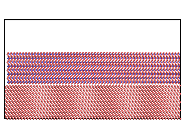
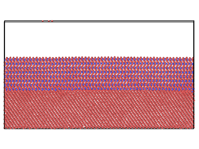
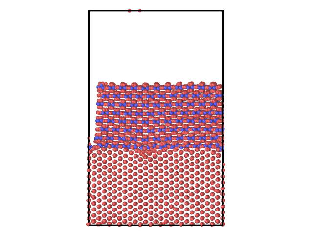
  • I am also concerned with the mismatch between the Fe and the cementite. Due to a difference between the lattice params of Fe and cementite, I searched for an integer number of cells in x and y such as the length of Fe is approx that of cementite (within 5%). However, the length of the cementite is a bit smaller (see picture). It is not possible to find exactly an integer number a cells such as it is exactly the same length. Since we would like to investigate the interface, I am wondering how this can affect it and if it does, how can it be solved.

  • Finally, I am also concerned by the periodic conditions that we are using in all directions. In z, we left a large empty space above the cementite in order to mimic an open surface so that Fe atoms do not interact with themselves through the PBC. However, in xy where we also use the PBC, we can see some interactions between the atoms occurs. Can this be avoided or minimized?

I leave some snapshot in order to show the different cases.

Many thanks in advance for any help you could bring me.
Christophe
PS: The LAMMPS version I am using 23 June 2022

atoms_before_minimization
atoms_after_langevin_nve
atoms_after_langevin_nve_2_no_minimization

These are not really LAMMPS questions, but questions about how to set up and equilibrate a suitable system for your specific purposes. What is “best” is often a matter of personal preference, expedience and need to accuracy or reproducibility. Those are topics best discussed with people familiar with your specific research or that you can learn from well done publications of similar systems.

Again, this is more about the science than about LAMMPS. If you have a mismatch in the lattice spacing between two adjacent layers of materials, you can always minimize it by setting up a (much) larger system. There is, obviously, a limit to that, so you will have to compromise. You will have one subsystem be slightly compressed and the other stretched in the end. You also need to keep in mind that you have to refer to the lattice spacing that you get from a bulk system of the same material with the exact same pair style and parameters, NOT the experimental data. There are often mismatches there, too. So you may need to do some bulk system relaxation first and the desired temperature, to determine the best parameters to choose. Details need to be discussed with people that have practical experience and are familiar with your research (like your adviser, supervisor, mentor, tutor etc.).

I don’t understand what you mean by this. If you want a layer, you want pbc and that means the atoms should interact. See my comments about finding a suitable lattice spacing.

If you want a “free” surface, you can just use “f” or “m” boundaries and there is no need to leave extra space. However, you will still have to properly handle the “bulk area” of your system. That is usually done by having 3 segments: 1) a bottom layer (1 or 2 atoms wide) with immobile atoms at previously determined bulk lattice settings, 2) a thermalized layer (a few atoms wide) where a thermostat is used to mimic the coupling to the bulk which is interrupted by simulating a truncated system, 3) a layer where only fix nve is used after initial thermalization, so that the system can behave realistically.
This setup is fairly standard and has been discussed in the past several times.

1 Like

Just a comment (not LAMMPS related) that may or may not be useful about:

However, in xy where we also use the PBC, we can see some interactions between the atoms occurs.

One thing that may help you have more “realistic” results for these interactions within the scope of classical dynamics at your surface interaction would also be to “terminate” it. For example, in my case, I have an solid/solid interface made out of ZIF-8 and a polymer. To terminate ZIF-8, DFT calculations were performed to evaluate which would be the most energetically favorable plane (i.e., more stable plane) to end the structure, believing that this would be likely to be the “occuring one” in real life. Cutting the interface always leave some high energy sites exposed which, based on a particular way this material is synthesize experimentally, are believed to eventually bond to -OH -H from water. So ultimately, in the place in which the xtal structure of ZIF-8 was cut, there are zinc cations coordinated to -OH and nitrogens, to -H. (Credits go to my supervisor who did this before I started on the project)

So, I dont know what is the precise context of your work, but maybe if you have “a terminated surface” (maybe a layer of iron oxide? idk), it may be useful for you to get more realistic results in your MD simulation also.

Hi Cecilia,

Thanks for your advice.
Actually, we would like to study the cementite in the bulk of Fe. Thus, in principle, we should study a system Fe/cementite/Fe (with PBC) and there should be no terminated surface. Here I showed the system Fe/cementite. I thought it would be simpler with only two layers and that with a thick enough layer of Fe and cementite, we would get the properties of the bulks.

Thank you Axel.

If I understand correctly, you suggest first relaxing each material separately with some equilibration scheme (eg langevin+nve) and then putting the two materials (Fe and cementite) together and relaxing the system. Correct?

No

Hi @Xtof,

Just to make @akohlmey point clearer here is a short version:

  • Compute the lattice constant you get from simulations at desired density in the bulk to know how your models behave.
  • Use these values in the making of your crystal interfaces. (Also remember that, as you have rotated crystal cells, the values you want to compare are the 1 cell dimensions along the x and y axes. But I guess you did that already.)
  • (Optional depending on your protocol) Keep fixed the position of some top/bottom layers by not integrating their motion (this can easily be done by assigning specific types to the atoms using smart combinations of region and group commands). These fixed atoms can act as a pseudo bulk for your other atoms to keep their structure far from the interface.
  • Run your simulations.

In the pictures you show the gap between the cementite images is also very wide so I guess there is a lot of stress in your surface anyway. As a rule of thumb I also try to have roughly square surfaces if possible but finding values close to least common multiple for dimensions is a more important thing.

1 Like

The opposite is the case.