Dear LAMMPS community,I’m attempting to simulate an amorphous silica system using the metal unit style in LAMMPS. The potential parameters (a hybrid of BKS and LJ) are strictly matched to a published paper,and Si atoms are assigned +2.4e and O atoms −1.2e. However, during runtime, the system immediately exhibits extremely large energy blowup.
Notably, the same simulation workflow works flawlessly with simpler potentials, so the issue likely stems from this specific potential setup. Below is my input script—any insights into why this happens would be deeply appreciated. I apologize for repeated questions, but I’ve been stuck for days and would greatly value your help.
newton on
units metal
atom_style charge
boundary p p p
timestep 0.001
read_data large_charge.data
pair_style hybrid/overlay lj/cut 5 buck/long/coul/long cut long 10 10
pair_coeff 1 1 lj/cut 12.6387 0.4200
pair_coeff 1 2 lj/cut 0.0112245 1.3100
pair_coeff 2 2 lj/cut 0.00035653 2.2000
pair_coeff 1 1 buck/long/coul/long 0 1.0 0.0
pair_coeff 1 2 buck/long/coul/long 18003.7572 4.8732 133.5381
pair_coeff 2 2 buck/long/coul/long 1388.7730 2.7600 175.0000
kspace_style ewald 1.0e-4
velocity all create 5000 98989
fix 1 all langevin 5000 5000 1.0 67890
run 10000
unfix 1
If the same input geometry works well with different potentials, then the culprit is how this potential is specified. Three issues:
- There is no time integrator in your script. Maybe you just forgot to copy it.
- The line
pair_coeff 1 1 buck/long/coul/long 0 1.0 0.0 is not needed.
- The cutoff for the LJ part is too small. At 5000 K, it’s no wonder it leads to large numerical errors and poor energy conservation (assuming there was a time integrator in the script you actually ran).
Side note: the damping constant may be too small, but maybe it’s just to slow down the dynamics. Try also the Nose-Hoover thermostat, fix nvt. Let us know what the results are.
Thank you very much for your valuable suggestions. Unfortunately, even after following your advice—increasing the cutoff distance and switching to fix nvt—the simulation still won’t run. It’s strange that the Vashishta potential works perfectly for the same system, though.
The potential energy shows that the initial guess is not suitable for this potential. Try adding a minimization step before running the equilibration, but I doubt that it will solve your issue.
Can you post the thermo output at step 0, computed with the Vashishta potential? Of course, using the same data file. Please just copy and paste the text output, quoting it with the </> button.
Thank you for your suggestions. I tried as follows:
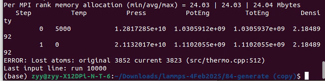
1.Energy minimization did help control the potential energy, yet the pressure remains abnormal, and the simulation still fails to run properly. Results:
Step Temp Press PotEng TotEng Density
426 5000 1.4956379e+09 88215662 2.1848992
427 0       2.3410467e+14 2.1418728e+12   2.1418728e+12 2.1848992
- When switching to the Vashishta potential (without energy minimization), the simulation runs smoothly. Results:
Step Temp Press PotEng TotEng Density
0 5000 255938.59 -28248.677 -25759.773 2.1848992
This is quite confusing to me, but thank you for your advice.
Can you post the reference of the paper with the description of the forcefield?
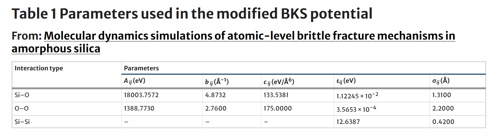
That’s quite useful. The direction of the dynamics shows that some atoms can cross the energy well of the Buckingham potential, which leads to strong repulsion --which is a rather suspicious behavior. You should be more proactive in this investigation, e.g. printing more thermo keywords and pin-pointing which term is likely responsible for the strong repulsion that you observe in the simulation My guess is that you misrepresented the potential, as the table reports the parameters b_{ij} in Å-1, while the buck style wants ρ in distance units. Invert the parameters and you should be good to go.
Going back and forth is not useful for you, nor interesting to me at this point. We learned that the problem is the potential used, as LAMMPS’ job is only to integrate (very reliably) the equations of motion.
1 Like
The DOI of the referenced publication is 10.1007/s10853-007-1638-2.
The force field is described as: *"The interatomic interactions were represented by a modified BKS potential derived from ab initio calculations [41]. The original BKS potential [...] was derived from restricted Hartree-Fock (RHF) cluster calculations [...] We use a modified form of the BKS potential as proposed by Corrales [41] to avoid unphysical effects at small interatomic distances that arise in the original BKS potential."*

You indeed pinpointed the crux of the issue right away.
Actually, a classmate had reminded me of this parameter issue at the very beginning, but I mistakenly assumed the parameters he shared had already been inverted, so I never bothered to test this adjustment  .
.
Thank you so much for your patient guidance—this experience has truly taught me a vital lesson in problem-solving.
Your mistake was to assume. I read the Manual™ instead.
Dear hothello,
Yesterday, I attempted to take the reciprocal of the parameter bij. Unfortunately, the system still collapsed immediately after running.
Subsequently, I explored previous community posts and found that some experts have developed more stable potential function tables, shared as files. I am grateful for their contributions.
Finally, thank you again for your patient guidance yesterday—your advice has been incredibly valuable to me.
Best regards,
Yifan Wang
Graduate Student
School of Power and Mechanical Engineering
Wuhan University,China
silica.tabulated (121.1 KB)
sio2.in (539 Bytes)
nanopore water simulations.pdf (613.7 KB)
1 Like
Hi all. I noted the potentials you are using. Let me say that the amorphization procedure is essential for reaching a properly relaxed amorphous structure, at desired P and T. I’ve been working withy silicates and it’s a little tricky work. If you have the computing resources for your system size, I suggest to use a reaxff potential. Charge balancing is a must and you must set te fix/qeq damping times correctly, and fine tuning depending on the thermal conditions. Finaly, let me say that the best way to get an amorphous SiO2 structure is to begin with a poscar crystal unit cell, properly replicated, an then use a melt-quenching protocol, Nayir paper describes this.(Redirecting), It’s only has an issue, but you will get it.
Thank you for your guidance. This is indeed a rather troublesome matter, and your suggestions have given me a complete train of thought-thanks.
1 Like
It’s a pleasure to help. By the way, I can provide you with a script I’ve been using for a couple of papers, regarding silica amorphization and also hydrogenation, using Monte Carlo exchange method. Let me know and I think I will be able to upload the files on this discussion.
Hi dtramontina,
Thank you very much for your kind offer and for sharing your experience with silica amorphization and hydrogenation. I’d be very interested in seeing the script you mentioned — it would be really helpful to compare with my current workflow and see how you approach the melt–quench process and Monte Carlo exchange.
Please feel free to upload the files here whenever convenient. I really appreciate your willingness to help and share your resources!
Best regards,
Yifan Wang
I must apologize for non catching the notifications of this topic. Time after, please confirm is the necessity is still valid so I provide you with some examples. Once again, my shame. Regards.