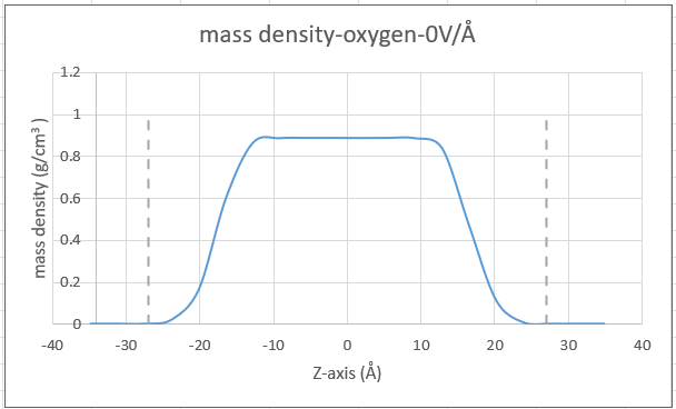
I have a system of Tip3p water with carbon walls placed in z-direction. So system is non-periodic in z-direction. I have calculated density profile for oxygen atoms using the fix ave/chunk command, but the result I’m getting is quite different from what I’d expect. In the attached Excel plot, which is my result, the dashed lines are the positions of the wall. There is a wide gap between the plot outline and the wall, as if the water is not touching the wall surface.
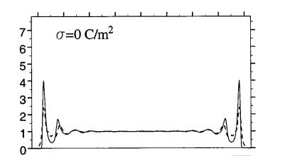
This is what I have seen in most literature. See a high peak at wall positions
I am not sure if my system has issues or I’m calculating the density profile incorrectly, that’s why I am asking for help. I have attached my input file here as well for context. Thanks and I appreciate any ideas and suggestions. Thanks. input-1.lammps (1.6 KB)
From a cursory look at just the two graphs without checking your LAMMPS input it seems like your system differs from the reference in that you have less water. You have a peak density of about 0.9 while the reference has about 1.0. Try moving the walls closer to the center or add more water molecules (about 15-20% from the looks of it).
Thanks Axel. Yes, you are right. The reference is actually for the whole water molecule, while mine is for oxygen. That’s where the difference in density is from. I will try to move the walls closer and revert. Thanks for the suggestion.
It looks like your graphene is super-hydrophobic; the density profile resembles that of a vapor-liquid-vapor slab system. My first guess is that the water oxygen-carbon LJ parameters are wrong.
Thanks Simon, that’s another thing I thought about because after moving the walls closer like Axel suggested, the same density profile still persists. These are the LJ parameters (real unit) for the system that I found in literature and used:
Walls (carbon): epsilon = 0.056, sigma = 3.4
TIP3P (O): epsilon = 0.102, sigma = 3.188. It’s 0,0 for H
If it helps, I started this simulation using the final configuration of an already equilibrated bulk water system. I created the fcc walls around it in Lammps, performed equilibration again with the walls in there, and gathered statistics. Thanks!
But how much closer? From a quick glance the interfacial density of oxygen is about half its bulk density at z = +/- 17 angstrom. That’s about where your walls need to be to see any sign of nanoconfinement.
You are simulating your water at a temperature where the liquid-vacuum interface is more stable than any creative alternative (since water’s vapour pressure is quite minimal at room temperature), and thus you should not expect the water to want to cling to the walls of its own accord unless (1) you have used extremely hydrophilic walls (patterned with high charge densities) or (2) you forcibly push the walls deep in enough to disrupt the interfacial profile.
tip3p is rarely the best choice to model water, there are some much better force fields like the tip4p series (2005, epsilon, etc.) that are known to better reproduce viscosity and other properties of water under ambient condition (Just look at how bad tip3p is doing in terms of NMR relaxation -which depends on both structure and dynamics of the fluid- when compared to experiments.)
choosing the right water-carbon parameters is still delicate. 10 years ago, the Amber force field was doing well when compared to quantum atomistic simulations in terms of water structure and dynamics, but there may be some better choice nowadays
I found that I never gave feedback on this problem. The problem was eventually solved by using a better water-carbon interaction parameter I found in a paper. That gave the desired density profile. Thanks.