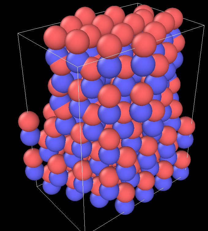
Hi,
I’m trying to create a grain boundary for ZnO, which has a wurtzite (~hcp) structure. I saw how to make grain boundary for cubic structures: https://icme.hpc.msstate.edu/mediawiki/index.php/LAMMPS_Help3#:~:text=LAMMPS%20Logfile,-Here%20is%20an&text=The%20grain%20boundary%20energy%20is,are%20dumped%20for%20post%2Dprocessing.
...
# ---------- Create Atomistic Structure ---------------------
lattice fcc 4.05
region whole block 0.000000 12.807225 -64.0361225 64.0361225 0.000000 4.050000 units box
create_box 2 whole
region upper block INF INF 0.000000 64.0361225 INF INF units box
lattice fcc 4.05 orient x  0  3  1 orient y  0 -1  3 orient z  1  0  0
create_atoms 1 region upper
region lower block INF INF -64.0361225 0.000000 INF INF units box
lattice fcc 4.05 orient x  0  3 -1 orient y  0  1  3 orient z  1  0  0
create_atoms 2 region lower
group upper type 1
group lower type 2

# ---------- Define Interatomic Potential ---------------------
pair_style eam/alloy
pair_coeff * * Al99.eam.alloy Al Al
neighbor 2.0 bin
neigh_modify delay 10 check yes

# ---------- Displace atoms and delete overlapping atoms ---------------------
displace_atoms upper move 0 0 0 units lattice
delete_atoms overlap 0.35 lower upper
...
However, for a hexagonal structure I’m not being able to create the lattice in the input script. It simply isn’t accepting the “xy” tilt.
Do you know if it’s possible to read a data.file (already with the correct wurtzite structure), and associate it with a lattice, or directly “orient” it, twisting or tiling crystals to create a grain boundary. Please what would be your suggestion?
Thank you in advance!
Best,
Gustavo Fortes
It would be more helpful, if you would quote your (failing) inputs rather than quoting an external source that is known to work.
i don’t understand what you mean by ‘It simply isn’t accepting the “xy” tilt.’ Whatever you do in your input has to be consistent with what the documentation describes, and not what you think it might do. We put significant effort into making certain that all available features are described in the documentation.
That said, nothing stops you from using a supercell, which can be orthogonal. Simply googling for “lammps wurzite” should provide helpful information.
You also seem to be misunderstanding what the lattice command does. It has no impact on the computation or geometry of a system whatsoever. It is simply a grid that provides convenient way to assign positions or determine volumes, just like ruled paper.
You can move and rotate groups of atoms around using the displace_atoms command.
ultimately, there are two general strategies for what you want to achieve. load a prebuild chunk of coordinates that is large than what you need, move and rotate as needed and then use a region to select the atoms to keep and delete the ones outside, or define those region(s), set a lattice geometry and then create atoms that fill that region. in both cases you need to be careful about overlaps; those can be handled when defining the regions or with the delete_atoms command.
axel.
Hi Axel,
Thank you very much for the insight of read_data and displace_atoms. It improved considerably! Almost a grain boundary.
Although, when I’m twisting the region upper the atoms get squished instead of not appearing. I was trying the lo/hi values INF for block or EDGE for prim, also initial cell size or larger -20 +20… Do you have any hint of how to solve this?
Thanks!
Best,
Gustavo

Script below:
REAX potential for Zn/O system
…Sigma 13 [0001] -> [001]
— Initialize Simulation
clear
units real
dimension 3
boundary p p p
atom_style charge
— Create Atoms
read_data ZnO_FullData444.xyz
#region whole prism EDGE EDGE EDGE EDGE -21.2273 21.2273 &
-6.5782 0.0 0.0
#create_box 2 whole
region upper prism -20 20 -20 20 10.61 21.2273 &
-6.5782 0.0 0.0
#INF INF INF INF
#EDGE EDGE EDGE EDGE
#0.0 13.1564 0.0 11.3938
region lower prism 0.0 13.1564 0.0 11.3938 0.0 10.61 &
-6.5782 0.0 0.0
group upper region upper
group lower region lower
displace_atoms upper rotate 1.64 4.74 0.0 0.0 0.0 1.0 27.8
— Force Field
pair_style reax/c lmp_control
pair_coeff * * ReaxFF_Potential_ZnOpure O Zn
neighbor 2 bin
neigh_modify every 10 delay 0 check no
fix 1 all qeq/reax 1 0.0 10.0 1e-6 param.qeq
---------- Displace atoms and delete overlapping atoms ---------------------
displace_atoms upper move 0 0 0 units box
delete_atoms overlap 0.35 lower upper
— Define Settings
compute csym all centro/atom 12
compute eng all pe/atom
compute eatoms all reduce sum c_eng
---------- Run Minimization ---------------------
reset_timestep 0
timestep 0.001
#thermo 10
thermo_style custom step pe lx ly lz press pxx pyy pzz c_eatoms
#dump 1 all cfg 25 dump.sig5_minimization_*.cfg mass type xs ys zs c_csym c_eng fx fy fz
dump coord1 all xyz 1 gbinitial_sigma13_0001.custom
run 0
write_data gb_position.txt
gb_position.txt (45.1 KB)
ZnO_FullData444.xyz (45 KB)
lmp_control (1009 Bytes)
param.qeq (55 Bytes)
ReaxFF_Potential_ZnOpure (21 KB)
gbinitial_sigma13_0001.custom (6.86 KB)
please review carefully what the various operations do that you have scripted. it is not what I suggested and not what you expect. just look at them step by step (which is how LAMMPS will execute them). keep in mind that LAMMPS is a computer program. it will do exactly what you ask for, whether it makes sense or not.
a) you are selecting a subset by region before moving them, not after
b) you are only loading a chunk of atoms once. if you displace part of them, there may not be any atoms for the second displacement in the area that you expect them in.
c) you are not deleting atoms outside the regions of interest. in fact, you should define the region “side out” not with the default of “side in”.
d) for this kind of setup it would probably be simpler much simpler to just define the two regions and “fill” them with atoms from a suitably oriented lattice (found this after googling a few minuts for “lammps wurzite” https://lammps.sandia.gov/threads/msg57334.html all you need to add are the desired orient options. for x, y, or z rotations.
axel.

