Creep test carried out by fix addforce

Hi, all
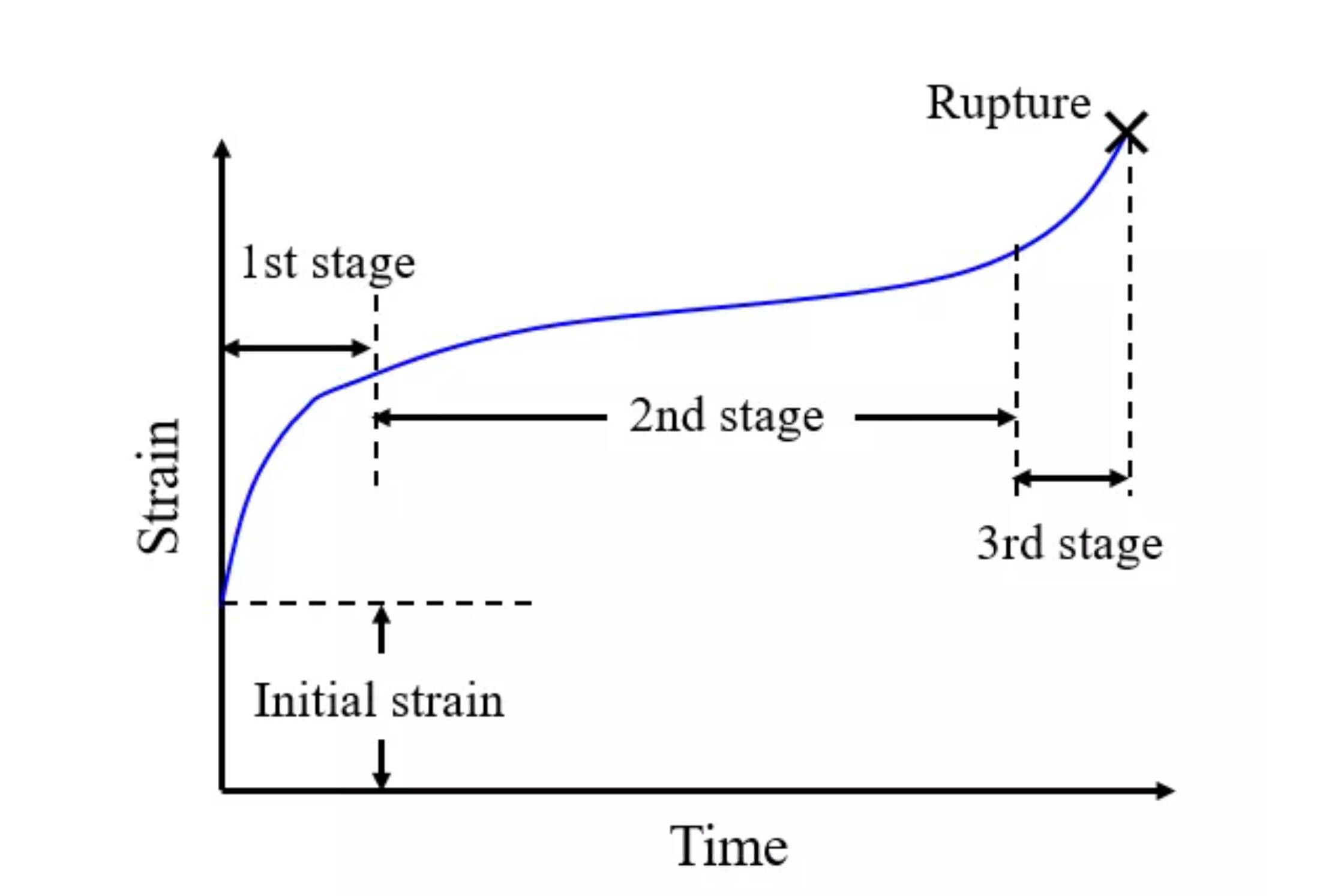
I am trying to simulate a creep test for a high entropy superalloy and draw a diagram with time vs. strain
Below is my input script
I omit the part of building the model in the script

#----------initial------------
velocity all create 1033.0 4846515
variable        TimeStep  equal 0.001
variable        Time	  equal ${TimeStep}*step
variable        T         equal 1033.0
variable	Pressure	equal 0.0
variable	TDamp		equal ${TimeStep}*100
variable        PDamp           equal ${TimeStep}*1000
#------ running ------
reset_timestep 0 
timestep ${TimeStep}
#------ stage 2 ------ run npt thermostat 
	#assign a random velocity to atoms at 1033K
region left prism  0.0 5 INF INF INF INF  0.0 0.0 0.0  units box
region right prism 163.16 168.16 INF INF INF INF  0.0 0.0 0.0  units box

group left region left
group right region right
group mobile subtract all left
compute 5    mobile      temp


velocity        mobile  create ${T} 4928459  
velocity        left create 0.0  4928459
fix freeze left setforce 0.0 0.0 0.0
fix  eq3 all npt temp ${T} ${T} ${TDamp} aniso 1.01325 1.01325 ${PDamp} 
fix_modify eq3 temp 5
thermo          1000
thermo_style    custom step temp c_5
run	  	6000

unfix eq3
#------ running ------
reset_timestep 0 
timestep ${TimeStep}
#-------prepare---------------------------------
variable        tmp equal lx
variable        L0  equal ${tmp}         #initial length
compute 3      right  displace/atom      #delta x(vector)
compute strainn right  reduce ave c_3[4]  #translate into scalar

change_box all boundary f p p
change_box all x delta -150 150 units box
#------ stage 3 ------ Store final cell length for strain calculations
variable        maxforce equal 0.1
variable        minforce equal 0.04
variable        totalrun equal 200000
variable        force    equal ${minforce}+((${maxforce}-${minforce})*step/${totalrun})

fix n1 all npt temp ${T} ${T} ${TDamp}   y 1.01325 1.01325 ${PDamp} z 1.01325 1.01325 ${PDamp} 
fix_modify n1 temp 5

fix d2 right addforce ${force} 0.0 0.0

variable strain equal   c_strainn/v_L0 #strain
restart		   40000  *_.restart
dump           d1 all custom 1000 strain_*.dump id type xu yu zu
dump_modify    d1 sort id  
thermo         1000
thermo_style   custom step  press temp c_5 v_L0 v_strain 

run           ${totalrun}

unfix n1
unfix d2
#unfix d2
unfix p1


the boundary is f p p
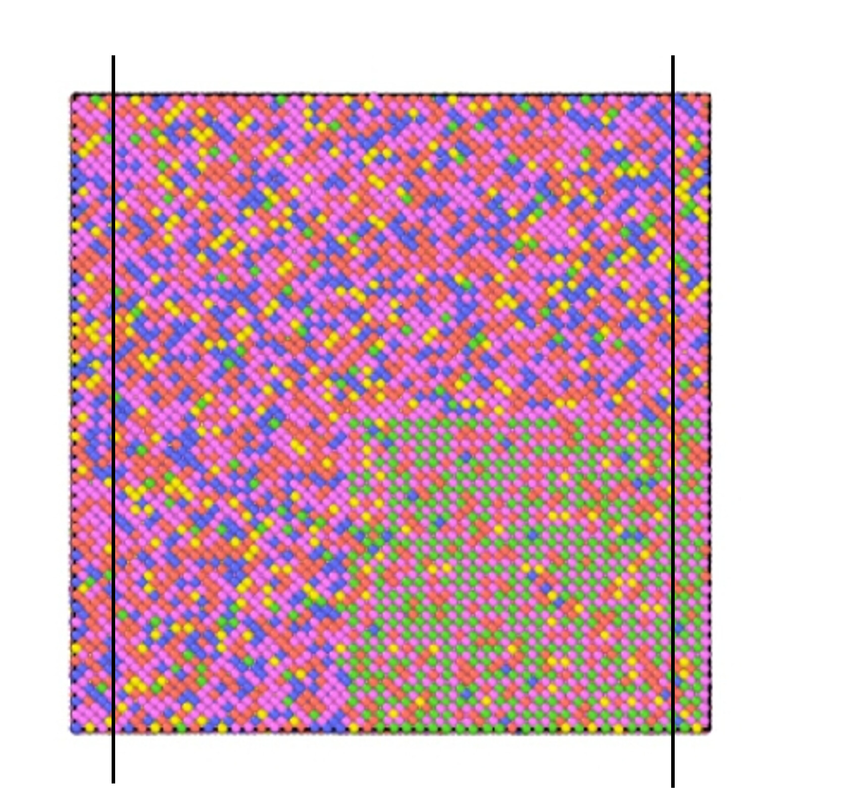
I divided the model into three parts as the picture above
I let the left part fix setforce 0.0 0.0 0.0
and the right part fix addforce in x direction
and get the video below

it should keep stretching rather than oscillating
how could I do to fix this
if there is any information I didn’t offer, please tell me

It is very difficult to give specific advice without experimenting with the system and investing some significant time and effort into possible alterations of the input.

Just three issues come to my mind directly.

  • shouldn’t you be using “m p p” boundaries instead of “f p p”, so that you don’t run a risk of losing atoms and problems resulting from that?
  • I don’t see any commands where the right (i.e. pulled) atoms are equilibrated and some velocity assigned. Without, you have to deal with those suddenly being let go and whatever effects result from that.
  • the whole setup would be far simpler when you move the atoms “on the right” with fix move instead of adding a force. That would remove the need to equilibrate and would enforce the uniform motion that you expect. Adding an increasing force is rather unpredictable. Is there a particular reason for that choice?

You equilibrated the box with PBC in x, but then turned off the periodicity in x before stretching. That is a drastic change to the system, setting off shock waves which are overpowering the steady state stress-strain response you’re hoping to see.

There is no easy way to model your system at specified, increasing stress, but you can get equivalent results by just stretching your box in x using (for example) fix deform without changing periodicity. For that matter, you should think carefully about periodicity in y and z – if you think you will observe necking and fracture, those look very different with PBC and without.

thanks for your replying
1.OK, I will try “m p p”
2.

group left region left
group right region right
group mobile subtract all left
velocity        mobile  create ${T} 4928459  
velocity        left create 0.0  4928459

I made the right atoms involved in the mobile atoms
and assign velocity to them
3. because in the real creep test, they do apply a constant force to the material, and see the change in strain with time
below is a classical diagram obtained from a creep test


I didn’t sure whether the fix move command can perform what I want to see because that will stretch the material in a constant strain, right?
but I’ll give it a try

But in an experimental test, that force is applied over minutes, at least seconds – you are hoping to finish your stress-strain curve in nanoseconds!

So either your results (and the experiments) will capture equilibrium, constitutive behaviour of the stress at a given strain, independent of the stress or strain rate – in which case the rate protocol doesn’t matter – or the behaviour you’re exploring is dependent on rate, in which case: it is impossible to exactly replicate experimental stress or strain rates in a simulation.