I am simulating a slab of a crystal between two layers of water.
To put the correct size for box in data file, I use the size of slab in x and z direction. In these two directions, I calculate the size according to the number of replication (cif file) minus half of bond length. In y direction, I calculate the size by sum of slab size (its number of replication) and the size of water layers. I use metal unit, and a time step of 0.001 ps. I have PBC in 3 directions. Other information are so:
minimize 1.00E-10 1.00E-10 70000 70000
neighbor 2.0 bin
neigh_modify every 1 delay 0 check yes
fix 1 water shake 1.00E-06 100 0 b 1 a 1
velocity water create 298.15 4928459 rot yes dist gaussian
In this system I have three problems. I appreciate any comment to help.
Thank you.
when I run nvt with the below command, I see a very high pressure of 30000 bar when I freeze the slab and 16000 bar when it is not freeze. I cannot figure out if this very high pressure is correct or some part of my simulation is wrong. I know that the slab is solid and this solid is very sensitive to even 0.1 A in size. But this is not my case. I want to know if this is a correct/normal pressure in such a system or I need to improve the input or data file to have a better pressure, let’s say 1 bar.
More information are that Pxx, Pyy … Pxy, … all, are very high when I freeze the slab and when the slab is not freeze, Pxx and Pyy are the only components that are very high.
fix 3 all nvt temp 298.15 298.15 0.1
velocity water scale 298.15
when I use npt with the below command, I see bubbles in the water layers. I am sure about the density of water when I use Packmol to build my system. Which part is wrong? how I can reach 1 bar without bubbles? I again cannot find which part is wrong.
fix 3 all npt temp 298.15 298.15 0.1 iso 1.00 1.00 1
velocity water scale 298.15
changing the method of minimization as below, could reduce pressure to 11000 bar but still it is high, and I see bubble in water even with NVT. In addition it changes the size of box from let’s say 107000 A^3 to 118000 A^3 before starting the production part of simulation. When I freeze the slab it arrives to 8000 bar and the size reaches to 109000 A^3 but still high pressure + bubbles are here.
minimize 1.0e-6 0.001 1000 10000
– isotropic volume relaxation to hydrostatic target
fix 3 all box/relax iso 1.5 vmax 1.0e-3
run 2000
– anisotropic volume relaxation to hydrostatic target
minimize 0.0 10.0e0 10000 100000
fix 30 all box/relax aniso 1.5 vmax 1.0e-3
minimize 0.0 10.0 10000 100000
– anisotropic volume relaxation to non-hydrostatic target
fix 300 all box/relax x 1.0 y 2.0 vmax 1.0e-3
minimize 0.0 10.0 10000 100000
minimize 0.0 1.0 10000 100000
minimize 0.0 1.0e-2 10000 100000
– Final refinement uses nreset to eliminate stress offset
fix 3000 all box/relax x 1.0 y 2.0 vmax 1.0e-3 nreset 100
minimize 0.0 1.0e-4 10000 100000
minimize 1.0e-6 0.001 1000 10000
run 2000
reset_timestep 0
Beside the three above cases, I wanted to ask the below question. Let’s call No.4.
4. Does the slab, made by replication of cif file in JMOL, need any minimization/optimization by DFT or MD before being used in Packmol to build the final system?
I guess the problem is in the way you build the slab. When making a supercell, you must stick to the crystal vectors: why do you subtract half of a bond length? (and which one?).
Secondly, I suggest you first minimise the slab in the vacuum, NVT, with 2D PBC with the kspace_modify slab 3.0 correction. Then add the water layer and revert to 3D PBC plus NPT with the barostat controlling only the vector perpendicular to the slab, that is, Y in your case.
I don’t understand this statement. The crystallographic vectors define translational symmetry. You created a supercell starting from the CIF file, then stick to the translation vectors of the supercell for your simulation box.
I guess the pressure difference is due to the relaxation of the slab. You can easily verify by visualising the trajectory.
Good luck,
Otello
It is difficult to discuss details of a simulation without actually seeing the data file and the complete input.
Some general remarks:
you cannot expect a classical force field model perfectly reproducing a crystal structure. So if you don’t allow the system to relax to “find” the geometry that is consistent with the force field, you will find residual stresses. Those residual stresses can be large for objects that are not very compressible and also this effect may be increase by having a small system size.
using fix npt with isotropic relaxation constraint is almost always a mistake for a slab geometry.
I don’t understand the notion of two water layers with periodic boundaries unless you add an additional complication with two water/vacuum interfaces (which does not seem what you are after). You would just have your slab immersed in bulk water. That you see two layers is merely a consequence of choosing the origin of your system, but periodic systems are translation invariant, so you can choose that origin arbitrarily.
I disagree with your confidence in packmol producing a physically meaningful geometry. It follows some simple, purely geometry constraints and knows nothing about physics. The need to further relax and equilibrate a system constructed with packmol is quite common. It just does a much better job than placing molecules in defined geometries with either a fixed or random orientations, which is the typical alternatives offered.
The best way to embed an object into bulk water is to generate a well equilibrated water box, then replicate it in such a way that it can contain the desired embedded object wholly. If this would be a slab configuration you have to choose the corresponding (water) box dimension to be an integer fraction of the final length and not allow that to change, so you will get a good fit. After replication to overlay both geometry and remove the overlapping water molecules. Mind you, you still have to do some relaxation to avoid water bubbles. since the contact regions will still need to relax and to avoid significant overlaps you usually need to remove more water than what would be a perfect fit after equilibration.
I appreciate the useful remarks. Thank you.
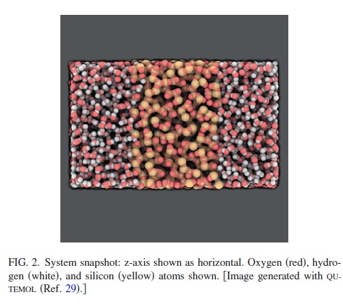
To clarify the system, please let me add a figure
of this article: https://doi.org/10.1063/1.3407433. The geometry of my system (water + slab + water) is similar to that but with different solid. I described the system as a slab between two layers of water. I must care about water to not leak since the slab does not look like a nano particle. So may I ask if the last point about the best way to build the system works for such a configuration?
Only to be more clear, please let me add the file that I use to generate the box by Packmol.new.inp (424 Bytes)
Thanks a lot.
I take your comment but since I use MEAM potential for the slab, I cannot use Kspace style and Kspace_modify when the box is without water.
It most certainly does. The procedure described in the publication you quote is equivalent. Only instead of overlaying a bulk water system, they just placed the pre-equilibrated water boxes above and below, but with perfect continuation through periodic boundaries. And then they did a careful re-equilibration procedure for the interface as would be needed for the variant that I described.