Dear all
I’m running into a problem after I constructed a polymer-sio2 interface model, I tried to set up the heat source and calculate the thermal conductivity in a follow-up study, but I ran into some problems during the pre-equilibrium NVT ensemble simulation, using the NVT ensemble simulation for the whole system (including the interface and the polymer), where there was a difference in the internal temperature of the system, which was manifested as a higher polymer temperature and a lower interface temperature, I didn’t understand why this was happening, even though I didn’t put any restrictions on the interface.

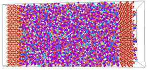
I draw a model with a silica interface on either side of the Z direction and a polymer in the middle, and simulate it under the NVT ensemble, and calculate the temperature distribution in the model slices (as a pretreatment before applying a heat source to calculate the thermal conductivity)
When fixing NVT on both sides and interface separately.
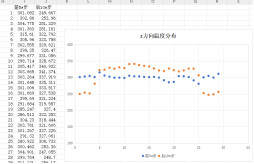
#First 1000000 steps (blue line below)#
fix 01 poly nvt temp 300.0 300.0 100.0
fix 02 group2 nvt temp 300.0 300.0 100.0
run 1000000
unfix 01
Unfix 02
#another 1000000 steps (orange line below)#
fix 01 all nvt temp 300.0 300.0 100.0
compute layers0 all chunk/atom bin/1d z lower 5 units box
fix 10 all ave/chunk 10 1000 10000 layers0 temp file temp00_profile.dat
run 1000000
It is found that the polymer and the interface are integrated together with the polymer temperature is high and the interface temperature is low, although the overall apparent temperature is still 300 K.

####chenge the after nvt to nve (no heat and cold source is set at this time, only the fix nve command), the temperature of the system will gradually increase, and the temperature of the interface between the two sides is still lower than that of the intermediate polymer phase, what are the possible reasons?
I don’t understand what the reason for this problem is, and how the system should be set up to make sense。
The in file and data file are as follows
msd400w.data (8.7 MB)
DENSITY.in (1.9 KB)