When I identified dislocations in a polycrystalline microstructure by using DXA, I got many dislocation networks on the grain boundary. It is very strange because the dislocation density is very large. For exemple, no dislocations are found when the model is built. But a large amount of dislocations are recognized by DXA after energy minimization.
Any leads on this is highly appreciated. In am having 3876000 atoms which I guess is a good enough size to simulate. The images are shown below
Thanks.

The DXA function of OVITO looks specifically for lattice dislocations and twin boundary dislocations in fcc crystals. If the crystal contains a grain boundary whose misorientation is close to a coherent twin boundary (i.e. a vicinal boundary) or a single crystal (i.e. a low-angle grain boundary), then DXA describes such a grain boundary as an array of dislocations. In other words, DXA interprets the grain boundary in terms of Shockley and Read’s dislocation model of grain boundaries.
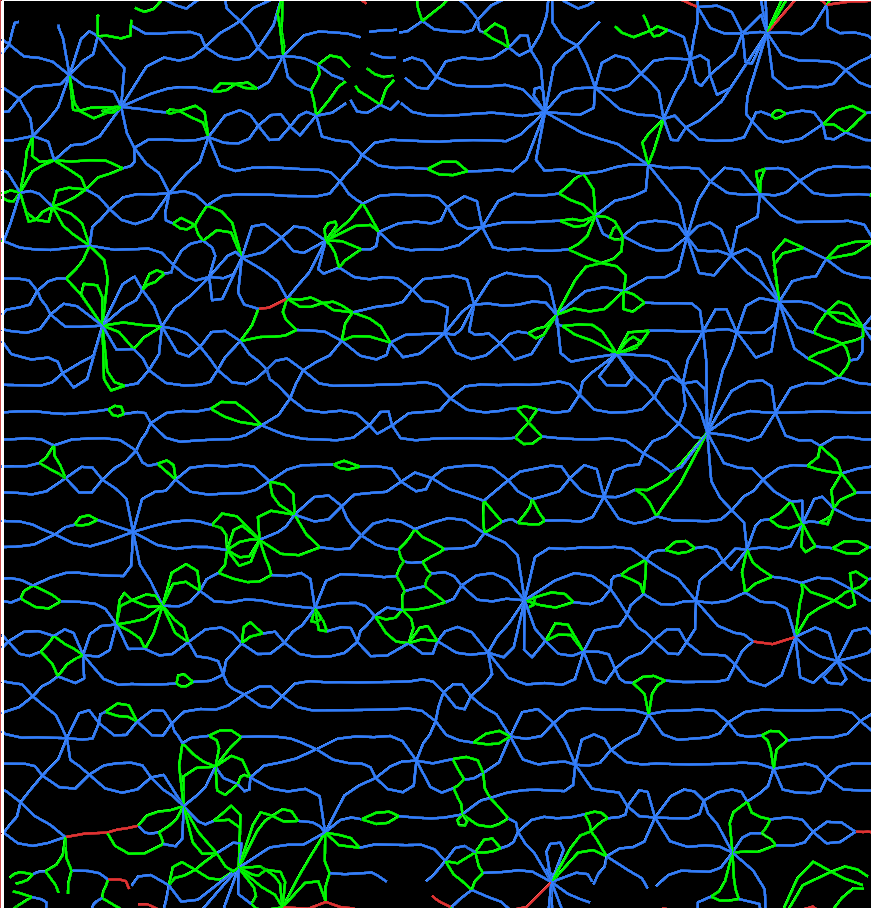
However, the capabilities of DXA are limited: If the density of grain boundary dislocations becomes too high (i.e. if it’s no longer a low-angle, but rather a high-angle boundary), and the dislocations partially overlap, then the algorithm can no longer recognize all of them. This results in gaps in the array of dislocations, as in the first image.
Thank you for your reply. But I would like to ask a question. There are a quantity of defects at the grain boundary itself. Will the DXA algorithm in Ovito identify the defects at the grain boundary as dislocations?
In addition, a large network of dislocations generated at the grain boundary for Figure 2, which doesn’t seem to be true. Is it possible for the DXA algorithm to identify fake dislocations?
I’m not sure if I really understand the questions - or why you are asking them. Could you please first post a picture of your grain boundary (atomistic representation, without DXA), showing only non-fcc atoms according to the common neighbor analysis (CNA) function of OVITO? This would help me better understand the situation and the (non-dislocation) defects you’ve mentioned.
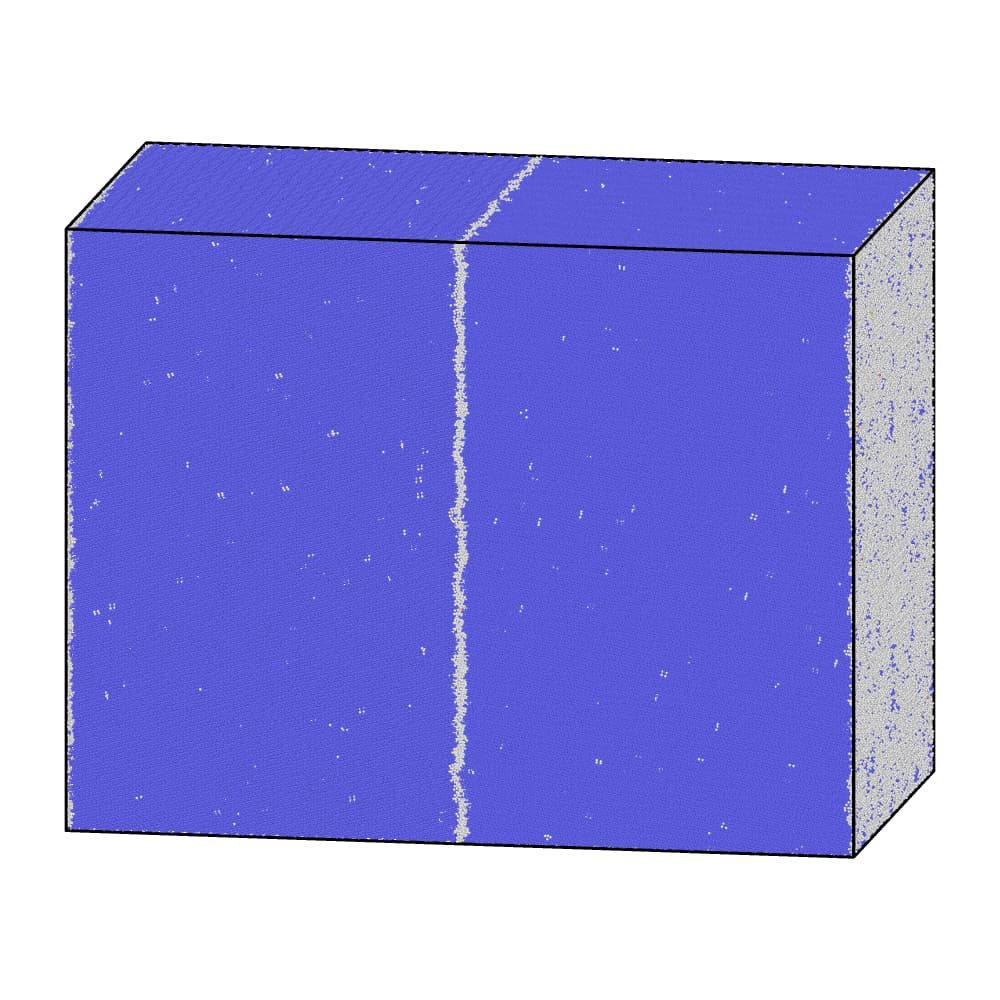
The CNA is shown in Figure 1, and the blue and write are represent bcc and other, respectively.
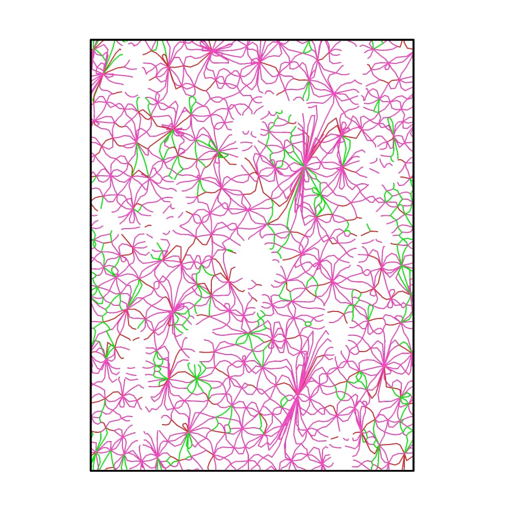
Figure 2 is the DXA analysis of another system at the grain boundary, it looks as strange as the figure above. Therefore, I want to determine whether the dislocations at grain boundary identified by DXA algorithm are true dislocations
I see, this actually is a bcc crystal. Under certain circumstances DXA treats such a bi-crystal not as two disconnected crystallites but rather as as a single crystal, i.e., as one continuous crystallite with a high lattice curvature concentrated in the grain boundary region. It then tries to find the GB dislocations that generate the lattice curvature in the Shockley and Read sense. This is why you see a dense array of lattice dislocations in the DXA output.
This happens whenever the GB contains one or more “bcc-like” atoms connecting the two grain regions. Such “bridge atoms” let the two crystallites appear as one contiguous region to the DXA, thus allowing DXA to trace paths from one side of the GB to the other and identify dislocations via the Burgers circuit procedure.
This phenomenon would not happen if the GB consisted entirely of “non-bcc” atoms (CNA structure type “other”), effectively isolating the two crystallites from each other.
Another way to prevent the link between the two grains is to first apply OVITO’s grain segmentation modifier. This modifier inserts an invisible “border” between the two crystallites, which effectively keeps DXA from tracing Burgers circuits across the grain boundary and identify dislocations inside the GB region.