Export visualizations for regions in LAMMPS to OVITO

@stukowski After working on this new LAMMPS command to visualize regions used in LAMMPS in VMD for the last few days, I am wondering, if there would be a desire to have something similar implemented in LAMMPS for OVITO.

I don’t know enough about the inner workings and low level scripting command options to figure this out by myself. I am still working on refining this feature for VMD where I am teaching LAMMPS to generate VMD script files to place graphics primitives into a “scene”.

Given the popularity that OVITO has with LAMMPS users and the fact that it doesn’t suffer from the restrictions of VMD, I could imagine quite some use cases in the OVITO community, probably more than for VMD. I mainly started this with VMD since I am deeply familiar with its script interface.

If there is anybody else interested in this (to use or - even better - to help implementing it), please respond here, or feel free to contact me personally.

P.S.: one generalization of this feature would be to do a full triangulation and have LAMMPS output the resulting data as a mesh in the STL file format.

Hi Axel, thanks for bringing this topic up. At OVITO, we also dealt with the question of how to enable users to visualize LAMMPS regions some time ago.

It looks like you approached the problem from the opposite direction. You have extended LAMMPS so that it can write suitable drawing commands for VMD into a file. We, on the other hand, had developed a function for OVITO that directly accepts LAMMPS region commands as input, parses them, and then visualizes the region boundaries in OVITO. This feature is documented here:

https://docs.ovito.org/reference/pipelines/modifiers/render_lammps_regions.html

At the time, we wanted to avoid making modifications to LAMMPS.

Our current approach has two fundamental drawbacks: (1) The user must manually extract the script commands from their simulation script and enter them in the OVITO GUI. (2) Our region command interpreter does not support dynamic regions, i.e., LAMMPS variables and lattice units don’t work.

Your approach is more elegant because it would make it possible to dump moving regions and convert the geometries into absolute length units. Right?

The fact that your new dump style generates graphics primitives for VMD is not ideal for directly integrating this file format into OVITO. I would prefer a new variant of the LAMMPS dump format that contains the regions in their original form and, for example, also contains information about the current MD timestep (e.g. when dumping a trajectory with moving regions). At the very least, such a file should include the region IDs so that the user can identify individual geometries in the vis application.

I agree, it is an open question where the triangulation of the region boundaries should happen: During the export from LAMMPS or during the display in the visualization application? Also, it is still unresolved how union and intersect composite region styles should be handled.

What is your opinion, can we agree on an even more general export format for regions? Or should we rather develop a dump style specifically for OVITO, like you did for VMD? We would be happy to contribute to the development.

Since the feature in LAMMPS is new, I am willing to refactor or rewrite it.
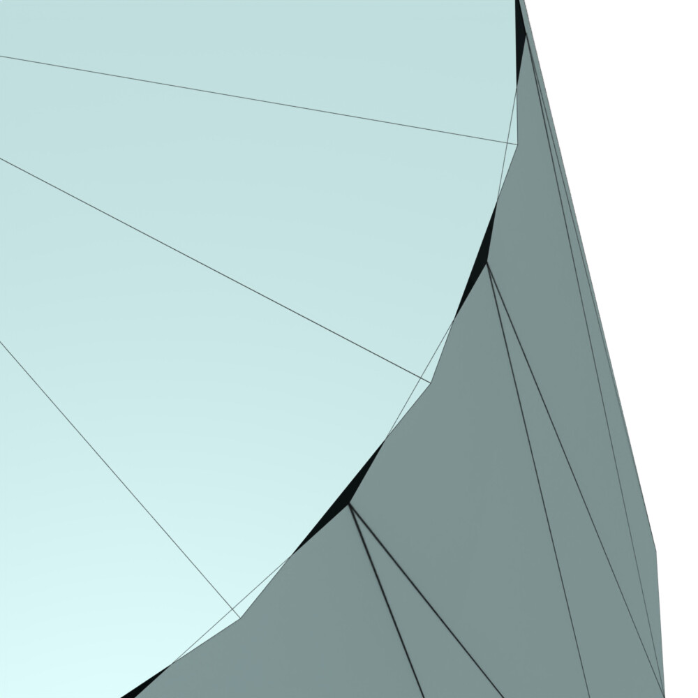
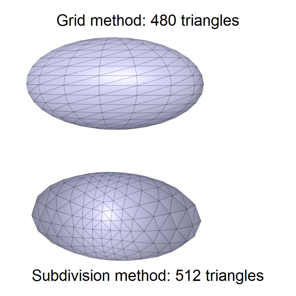
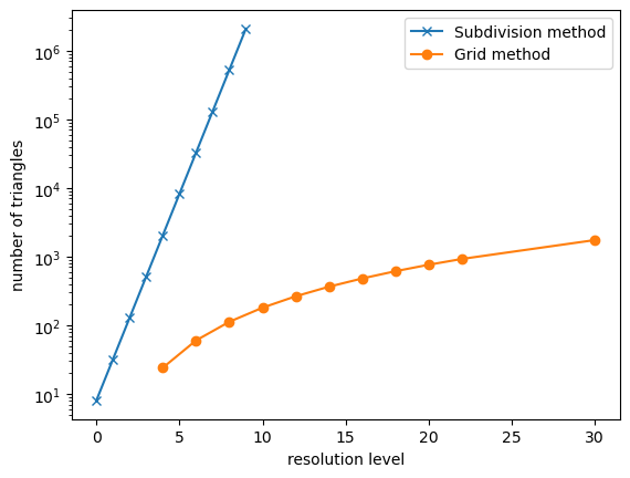
While I started with trying to directly translate LAMMPS regions into VMD graphics primitives, I am slowly moving toward doing a full triangulation in LAMMPS and then output just triangles or triangles with norm vectors at the tips for smoothly rounded surfaces. This way, I can visualize the cone region and the cylinder becomes just a special case of a cone, same for ellipsoid and sphere. The block and prism styles are made from pairs of triangles for each side and plane is still in development, but could be built from 4 triangles around the center point.

Intersections and unions are - at the moment - too hard a problem. They are easy to handle in LAMMPS since for the use of regions, LAMMPS looks at atoms, i.e. whether the coordinates fit into all or one of the combined regions. Visualizing them is harder, but people can still visualize the constituent regions and by switching colors one could tell them apart.

The more I think about it, the more I am leaning toward creating a generic class that does the triangulation for all supported regions and stores the information internally. Then there could be multiple commands to output this information in different file formats. So not just VMD script, but also, say, STL. Then there would be multiple commands, region2XXX that will output the triangulation in a different formats. That would also elegantly solve the issue of moving or rotating regions, since that transformation can be performed separate (and only if needed) from generating the triangulation. The latter could also include flags, whether a region has a variable shape or is fixed and then the triangulation only needs to be repeated for those with a variable shape.

That would be problematic for anything that uses variables, i.e. shape, movement, or rotation.

My current feeling is that having different back-ends would be more suitable, since it allows to “optimize” how the data is organized for the visualization tool/strategy at hand. Since most regions are static, I have started with a simple command that creates a single file for a single timestep. In VMD I would have to use VMD/Tcl scripting and for visualizing a trajectory, I would need write a script that stashes away the triangulation data into an “array of structs” and then connect the coordinate dump file step with the matching triangulation data. The cleanest way in VMD to handle this (and allow people to individually turn region visualizations on or off) would be to create an empty “molecule” for each region and then add the graphics primitives to that. This is what I currently have. and then the VMD main window would look like this.


By clicking on the “D” character in each line for a “molecule” the region can be hidden or displayed and the “molecule” name includes the region ID.

And below is the VMD input to generate this. I then run ./lmp -in in.input and then visualize with vmd -e cylinder.vmd. The “command” keyword in the region2vmd command, allows me to insert custom VMD script commands, so that the resulting .vmd file can be used as a VMD state file and loaded accordingly and will load the dumped coordinates as well. Of course, a region2ovito command could handle this in a way that is optimal for OVITO.

units real

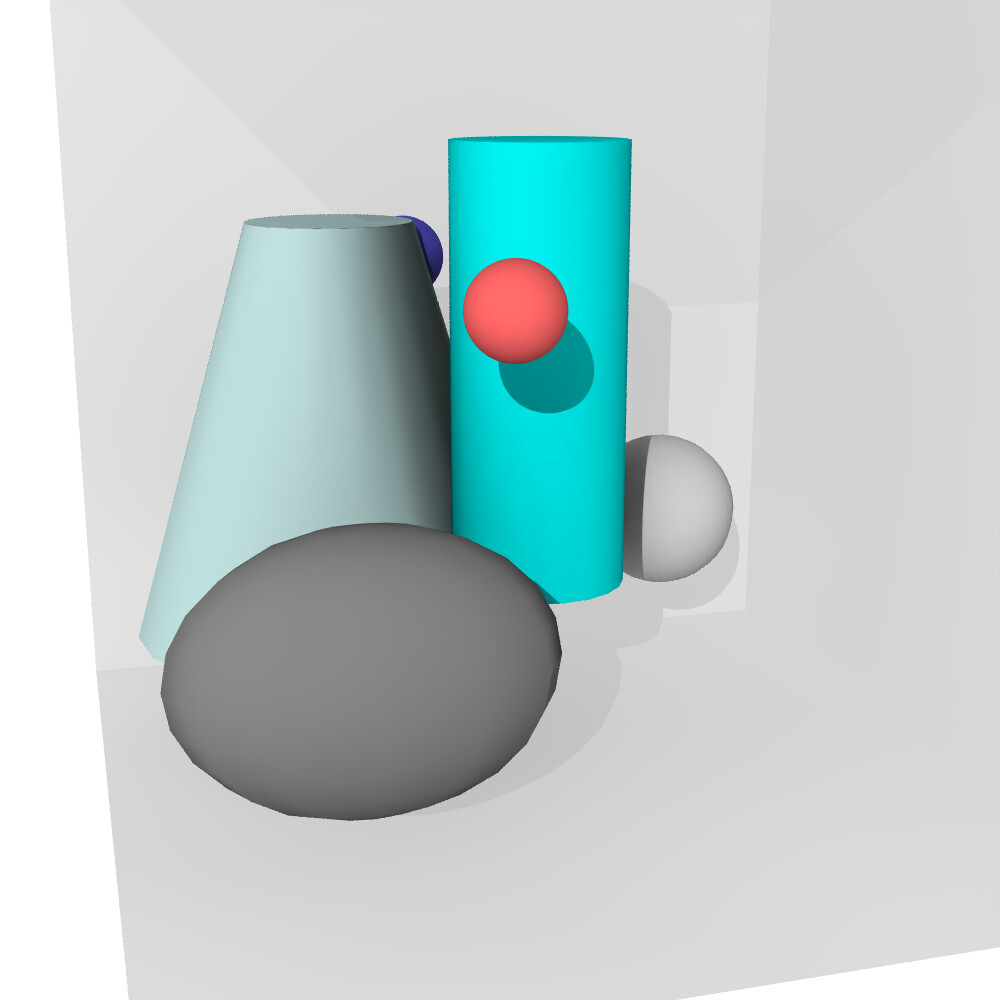
region box block 0 20 0 20 0 20 open 1 open 4
create_box 2 box
mass * 1.0

region sph1 sphere 15 5 5 2
region sph2 ellipsoid 5 15 5 2 4 3

create_atoms 1 single 5 12 12
create_atoms 2 single 15 12 12

variable xxx equal -2.0
region c1 cylinder z 10 10 2 5 15
region c2 cone z 14 14 5 2 5 15 move NULL NULL v_xxx

run 0 post no

write_dump all atom cylinder.lammpstrj

region2vmd cylinder.vmd command "mol default style VDW" &
    command "set oldtop [mol new cylinder.lammpstrj waitfor all autobonds off]" &
    command "axes location LowerLeft" region box &
    material Diffuse color iceblue region c2 color cyan region c1 &
    color white region sph1 color gray region sph2

I want to start by writing a command for a single static visualization to be used in combination with a file generated by write_dump or write_data, and then develop a corresponding dump style on top of that. I see that there could be at least four back ends: VMD, OVITO, STL, and VTK.
Since we already have an option for exporting VTK, the logical step would be to expand that dump style. For STL output, we would have to enforce the one file per timestep option with embedding a star character in the filename. VMD will have to use a mechanism similar to what is used in my 20+ year old tutorial on dynamic data with VMD: Visualization and Analysis of Quantum Chemical and Molecular Dynamics Data with VMD. In this case a region2vmd dump style would have to be given the dump ID of a trajectory dump with coordinate data, so the VMD script can be synchronized with it. It is very likely that OVITO needs the data in a different style (unless you want to write a parser for VMD script commands and translate them to OVITO), so it would be up to you define it. If you prefer a custom format, it would be straightforward to follow other LAMMPS dump style conventions with “ITEM: XXX” tags and the corresponding information following.

My plan is to start the refactoring according to what I have outlined here soon, I can make the branch public and then we can work on the details and the various back ends together, either by you commenting on the code and making suggestions for (small) changes or by submitting pull requests for larger changes.

Please let me know what you think about my plans.

Yes, what you suggest sounds good. The triangulation can be done in LAMMPS, we don’t need the regions in parametric form in the visualization app.

OVITO can already read STL, OBJ and certain forms of VTK files (static or as animated file series if desired). So these might suffice if you are going to implement export backends for some of them anyway. My only concern is that the STL and OBJ formats (and also the legacy VTK format) do not support multiple separate objects. So they are not well suited for storing multiple regions and their identifiers. The more powerful, modern XML-based variant of the VTK format can be an alternative, as it supports datasets made of named parts.

Your suggested design keeps open the possibility of implementing a new special exchange format for OVITO after all, if this is useful - or we might even want to support the VMD graphics scripts in OVITO, yes. I might try to generate such a file to have a look at it.

If you check out the current LAMMPS develop branch, you can use the example input I posted and run it and it will generate a VMD/Tcl script. The corresponding VMD commands are documented here: https://www.ks.uiuc.edu/Research/vmd/current/ug/node129.html

I built a small OVITO prototype to read the example VMD script, and so far it seems to work really well. The file reader is available on my github.

I used different methods for triangulating the sphere and the ellipsoid, so the resolution parameter is interpreted slightly differently, leading to small visual differences in appearance. However, this could also be adapted if needed.

I have three open questions:

1. Is there any unique marker in this file format to identify it reliably?

Currently, I rely on the .vmd file extension in combination with the first two lines:

# save old top molecule index
set oldtop [molinfo top]

to deduce the file type. This doesn’t feel entirely robust. Would it make sense to include a unique header line to clearly identify the file format?

  1. Why is the cone output as a set of triangles, combined with two cylinders as caps?
# region c2 of style cone
...
draw trinorm {13.687131069919538 15.975376681190276 13} {14 19 3} {14.312868930080462 15.975376681190276 13} {-0.15643446504023087 0.9876883405951378 0} {0 1 0} {0.15643446504023087 0.9876883405951378 0}
draw trinorm {14 19 3} {15.545084971874736 18.755282581475768 3} {14.312868930080462 15.975376681190276 13} {0 1 0} {0.3090169943749474 0.9510565162951535 0} {0.15643446504023087 0.9876883405951378 0}
...
draw cylinder {14 14 3} {14 14 3.00001} radius 5 resolution 20 filled yes
draw cylinder {14 14 13} {14 14 13.00001} radius 2 resolution 20 filled yes

Wouldn’t it be simpler to output either only triangles or use the cone primitive directly? I’m asking mainly because my prototype currently renders a mismatch between the cone sides and the top cap:

This is certainly fixable, but I’d only invest the effort if the cone output format is not changing later on.

3. Would it be possible to output triangle normals for the “block” region?

# region box of style block
...
draw triangle {0 0 0} {0 0 20} {20 0 0}
...

While it’s possible to reconstruct the normals from the geometry, it might be more convenient for users of the format if the normals were included explicitly.

No, but it can be easily added as a comment. We are doing a similar thing for the comments in LAMMPS data files.
That way there can be additional information given that may be useful, e.g. (I am open for suggestions):

  • number of trajectory frames with distinct lists of graphics primitives (for a future variant for trajectories with moving/rotating regions
  • format revision (so modifications can be made and any parser can adjust)
  • flag whether a designated trajectory file to match the primitives is named

The LAMMPS cone region is more flexible than the VMD cone primitive. It can be truncated at the top and be open on top, bottom, or side. The cylinder caps are due to laziness and for historical reasons. I am thinking about refactoring the implementation to only rely on “triangle”, “trinorm”, and “sphere” primitives and do the entire triangulation within a class in LAMMPS. That would also allow to apply translation and rotation consistently at that stage.

I believe that good software is written at least three times: first time to figure it out at all, the second time to get it done right, and then to make it work well. I think this feature is somewhere between step one and two right now.

I have come to the same conclusion. Also this way a cylinder is just a special case of a cone.

Technically, yes. However, I don’t know what that would do to what graphics VMD generates from them. The “triangle” primitive does exactly what is desired to match the geometry, so I didn’t bother to also construct normals.

As a long term perspective, it may be preferable to create a custom file format suitable for easy parsing in OVITO that is compatible with trajectories. I would also entertain the ideas of adding these graphics objects to VTK format dump files and output STL meshes (with the one file per frame convention). This is currently in the planning stages and it will take me some time until I can work on this due to other commitments.

If you have specific requirements or preferences, I suggest you submit a “Feature request” issue in the LAMMPS GitHub project so that this is not “lost”. Posts in a forum have a risk to be forgotten by the time one gets around to working on this. I am also open for a direct collaboration on the LAMMPS code if you have some ideas for an OVITO-specific output approach.

Thank you for your feedback. I definitely agree with the statement that software is written multiple times—this is precisely the reason I built the OVITO prototype.

Having a descriptive header would be very helpful for us. Given the wide range of file formats supported by OVITO, robust automatic format detection is key. I don’t think we require any additional information.

Considering the typically small number of triangles involved, this would be a good solution.

Apart from that, I feel that parsing and using the existing file format is actually quite reasonable, so I’m not sure there’s a need to develop a custom format specifically for OVITO.

Ellipsoid Triangulation

The method used to generate the triangle mesh for the ellipsoid (subdivision method) doesn’t offer much control over the number of triangles—assuming I’ve correctly translated your Tcl code into my Python prototype.

I implemented an alternative approach (grid method) which distributes triangles on a grid across the ellipsoid and allows for finer control over the resulting number of triangles.

The differences can be seen in the following figures:


image

If this is something you’d be interested in, I’d be happy to submit a corresponding feature request. If you don’t see a need for a different triangulation algorithm, that’s also completely fine—I’ll just save the time and skip the feature request.