Please send future correspondence to the mailing list. There is no fundamental difficulty with calculating 2D elastic constants using a modified version of the existing 3D script given in examples/ELASTIC. However, you need to understand a few things:
- Graphene atoms move in 3D, it is only the crystal symmetry that is periodic in two directions
- 2D elastic constants are defined in terms of a 2D stress tensor, units are energy/area
- The LAMMPS stress tensor is always 3D, units are energy/volume
- You can recover the 2D stress tensor from the 3D stress tensor by
discarding components in the non-periodic direction and multiplying
by the somewhat arbitrary thickness in that direction
- Make sure you turn off the periodic boundary condition in that direction
- There are probably a few more issues that don’t occur to me right now
- To deal with 6, you should construct a simple problem where you know
the correct answer
- Keep fixing the script until you get the right answer.
Aidan
1 Like
Dear Thompson:
If i want to calculate the Young’s Modulus of a 2D crystal structure (such as graphene), could i perform uni-axial tensile (“fix deform” command in lammps) of graphene in two-dimensional space (set the dimension command in lammps as “dimension 2”)? or must set as “dimension 3”? looking forward for your reply! Any tips will be grateful?
Xuepeng
You could do it either way. I think it is better to allow for the possibility of out-of-plane motion, although for perfect grapheme sheet, there probably will not be any. As soon as you create a defect, such as dopant, you can expect to see out-of-plane relaxation.
Dear Thompson:
Thank you very much for your comments! I performed uniaxial tensile simulation of 2D crystal structure in dimension 2 and dimension 3 before, but i found that the Young’s Modulus of 2D case is almost two orders of magnitude greater tnan that of 3D case! this confused me a lot, for the experimental data shows that the Young’s modulus of 3D and 2D materials (same materials) are almost several GPa, my simulation result showed a Young’s modulus of several GPa in 2D case, which agrees well with experimental result.however, the Young’s modulus of 3D case in my simulation is two orders of magnitude less than 2D case, which do not agree with experimental result. what i would like to ask why the simulation result of Young’s modulus of 2D case is much larger than 3D case ? looking forward to your reply! Any tips will be grateful!
best wishes
Xuepeng
I can’t say what the reason is, because it depends on the details of the simulations. However the general method is very simple:
- Apply an axial strain and measure stress before and after
- You may or may not want to relax atom positions after applying strain
- Divide the change in the axial stress component by the change in the axial dimension.
- Verify that this ratio is roughly independent of the strain magnitude.
- Convert ratio to elastic modulus in appropriate units by applying appropriate scale factors
- Results in 2D and 3D should be similar
Dear Thompson:
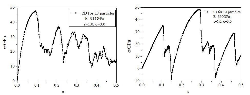
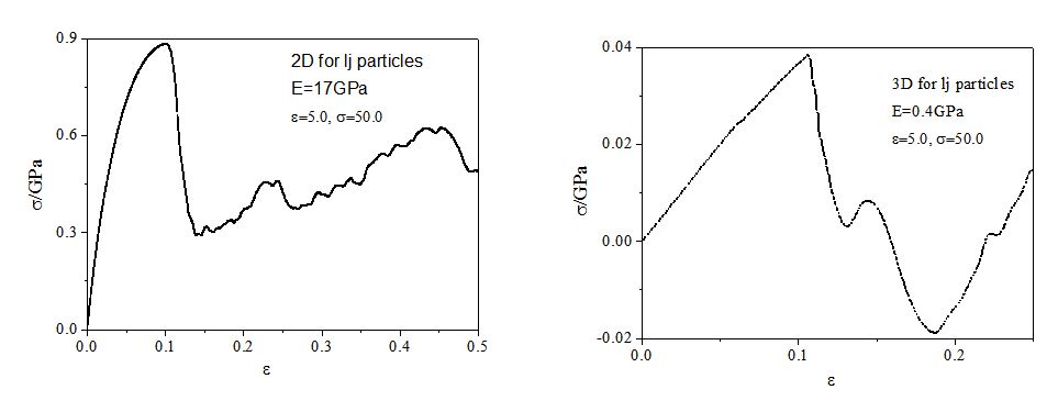
Thank you very much for your guidance! My simulations almost meet your advice of the general method, indeed, the simulation result depends on the details of the simulation, and the difference between 2D and 3D case is strongly related to the pairwise interaction potential between particles! I used two kinds of LJ potential:  , one is epsilon=1.0, sigma=3.0. the other one is epsilon=5.0, sigma=50.0.In the former case, the simulation results of Young’s Modulus in 2D case is 911GPa, in 3D case the Young’s Modulus is 350GPa, and their uniaxial tensile curve shape are similar (the result is represented in 1.JPG), this meet your general method of 5 “Results in 2D and 3D should be similar”. however, for the latter case, the simulation results of Young’s Modulus in 2D case is 17GPa, but in 3D case is 0.4GPa, the 2D case is almost two orders of magnitude larger than 3D case! and their curve shape are different (the result is represented in 2.JPG). What’s your opinion on the difference of simulation results of 2D and 3D case by using the two kinds of LJ potential? In addition, my research is on the study of the mechanical behavior of bulk nano materials composed of nanoparticles, and the interaction potential between nanoparticles is similar to LJ pairwise potential (treat one nanoparticle as a single point). Looking forward to your reply! Any tips will be grateful!
Sorry to enter into the conversation, but shouldn’t be easy to plot E vs tbe distorted unit cell , and then find the elastic constants from the second derivative of the energy vs the strain ? (at T =0) …I mean you only have to do distortions along each of the unit directions, eg : x, y ,z ,etc
A Salute
Oscar G.
Dear Oscar:
Thank you very much for caring about this topic! i am sorry that i don’t really understand your comments. indeed, the elastic constants can be derived from the second derivative of the energy vs the displacement (my case is T=300K), and my tensile direction is along x axes. and the elastic constants can be determined by fitting the beginning part of the stress-strain curve to a straight line (the beginning part of the curve is almost linear). thank you very much! any tips will be grateful!
best wishes
Xuepeng
Hi, all
Can somebody give me some explanation about my doubt? thank you in advance!
best
Xuepeng
What is your doubt? Is it a doubt about LAMMPS?
Ray
Please reply to the mailing list not to me, thanks.
Of course you can, and you should obtain comparable results. What is causing the confusion is probably the result of the potential you used - which may be too simple to capture the difference.
Ray
Hi,Ray
Thank you for your comments!best