I had created GULP input files by Materials Studio (Materials Studio stated GULP supports calculation only in P1 space group). The generated .gis works OK with Materials Studio independent Windows GULP build …
If I modify the files to describe the structure by the help of space group (tested P21, P-1) the geometry optimization generate nonsense …
Any idea what is wrong ?
The nonsence generating .gis follows (DMSO structure) :
Hello Michal,
Obviously, the connectivity is not set correctly. Add the “mole” keyword, remove “noauto” from the input line, and also remove all the “connect” directives. They seem to be incomplete. I checked your input using gdis and certain bonds appear broken. The input I suggest above, works fine for me (Gulp 6.2 compiled on windows11 by mingwin/msys). Also, it might be better to add charges.
The input was working OK in P1. I had only removed the symmetry generated second molecule and changed space group from P1 to P-1. So it is impossible the input is wrong.
The connectivity is correct for 100%, it can be checked easy manualy based on the DMSO formula.
How can I remove “connect” directives from the file, when they gives the code the instruction witch forcefield constants should be used ?
GULP is not able to identify atom types and bond types for forcecfields automaticaly - this must be specified.
Can you, please, post the input witch works for you ?
library C:"path to dreiding library file"\dreiding.lib (this modification may not be necessary in your case)
output cif DMSO-out
The above input produces reasonable results. Nevertheless, the use of P1 together with a defined connectivity may be necessary for the dreiding force field, due to the way it calculates torsions. I believe prof. Gale can clarify this.
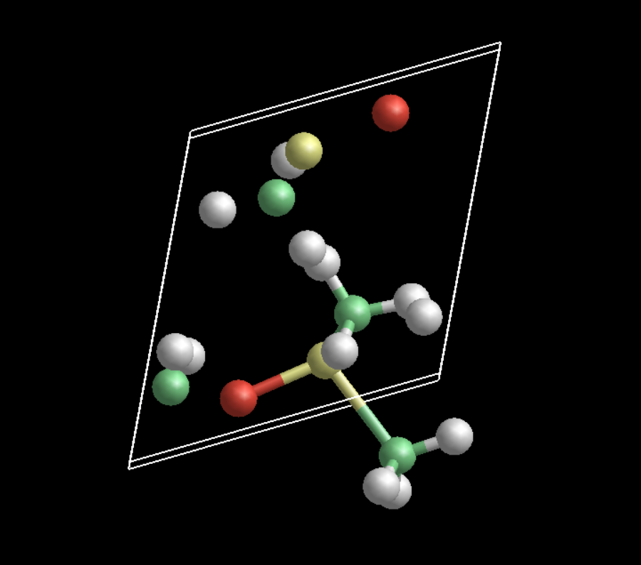
This is what your original input produces in gdis. This is corrected by removing the “noauto” keyword. The “mole” keyword isn’t really necessary if you remove the “noauto”, and you can also keep the “connect” directives.
Thank you for the image. It sounds lik gdis or GULP do not work correctky with symetry operations. Insead of only applicating symmetry operations they in addition shift the symmetry generated atoms back to the unit cell. This should not hapen, becouse it breaks the connectivity. Such handlink is OK only for DFT calculations, not for force fields …
Thank you for the input file - I will check the results against reference Dreading implementation to see the force constats were correctly assigned.
I am almost sure your input creates S-O single bond instead of S=O so the result can not be correct (becouse automatic GULP bondings assign single bond to everithing).
I can confirm your input generates 100% identical results as reference Dreading calculation (done in Forcite+ code in Materials Studio, space group P1). It works in this case because Dreading force field does not identify the force-fields parameters based on bond type but based on atom types (so it ignores the single bond information and handle S_3-O_2 as S=O. I am not sure if this can work for more complex force fields when bond type (typically resonant) recognition will play a rule … But maybe resonant bond will be covered good enough by the atom type …
I still wonder what is GULP doing when it apply symmetry operation . For non covalent bonded inorganic structures it give sense to shift the symmetry generated atoms back to the 0-1 fractional coordinates range, but this is not the case of molecular crystals when bonds should be specified …