generating a perfect edge dislocation

Hello,

I am trying to generate an edge dislocation that should traverse through the x direction as the box is sheared. For this purpose my approach was,

  1. I generated a triclinic box with the desired FCC composition and relaxed it.
  2. Then I took the dump file and deleted a half plane of atoms after which the box looks like what is shown below. I saved it as lammps data file and used it for the next simulation.

image.png

  1. I subject this triclinic box to Shear strain but I don’t see the edge dislocation traversing perfectly. I see a mixture of dislocations as shown below.

image.png

What I wanted is a single perfect edge dislocation traversing from the left to the right.

My code is attached below.

units metal
dimension 3
boundary p p p
atom_style atomic

----------------------- ATOM DEFINITION ----------------------------

read_data disloc.data

Depending on the shear rate you apply, as well as
boundary conditions, the size of your system,
how well you have relaxed it before shearing, etc
you may get different behaviors. I suggest starting
without shearing and see if the system stays
stable.

Steve

image.png

image.png

Thank you for your reply.
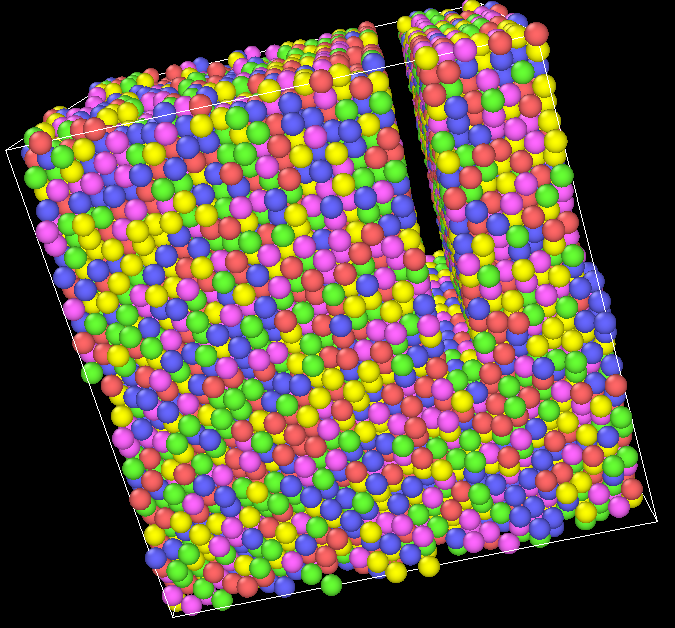
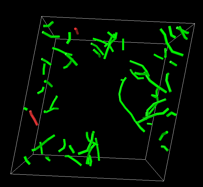
I tried to achieve the same (hard particle in an alloy matrix) by using in.shear example from lammps examples and it is able to generate dislocations well. I wanted to calculate the shear stress at the same time so I am using compute stress atoms to get the stress in the mobile region. I have marked it in bold in my code below.

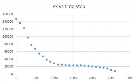
The problem is that I see a decreasing shear stress. I would expect an increasing trend since we are shearing the box and the stress should rise with strain.
Could you kindly tell me where I am going wrong?

Also what would be an ideal approach to calculate the shear strain in this example?

image.png

units metal
boundary s s p

atom_style atomic
lattice fcc 3.52
region box block 0 16.0 0 10.0 0 8 #2.828427
create_box 7 box

lattice fcc 3.52 orient x 1 0 0 orient y 0 1 1 orient z 0 -1 1 &
origin 0.5 0 0
create_atoms 1 box

variable fa equal 50000
variable fb equal 37609
variable fc equal 24933
variable fd equal 12421
variable fe equal 10
variable ff equal 1
variable ft equal 62500

set type 1 type/fraction 2 (v_fa/v_ft) 1734536 set type 2 type/fraction 3 (v_fb/(50000)) 1734535
set type 3 type/fraction 4 (v_fc/(37609)) 1734534 set type 4 type/fraction 5 (v_fd/(24933)) 1734533
set type 5 type/fraction 6 (v_fe/(12421)) 1734533 set type 6 type/fraction 7 (v_fe/(12457)) 1734533

group Co type 1
group Cu type 2
group Cr type 3
group Fe type 4
group Ni type 5
group W type 6
group Al type 7

pair_style eam/alloy
pair_coeff * * CoCuCrFeNiWAl.set Co Cu Cr Fe Ni W Al

neighbor 0.3 bin
neigh_modify delay 5

region lower block INF INF INF 0.9 INF INF
region upper block INF INF 6.1 INF INF INF
group lower region lower
group upper region upper
group boundary union lower upper
group mobile subtract all boundary

set group lower type 2
set group upper type 3

void

region void1 sphere 8 3.5 3 2 side in
create_atoms 1 region void1
group void1 region void1
set group void1 type 7

region void2 sphere 8 3.5 3 1 side in
#lattice bcc 3.17 orient x 1 0 0 orient y 0 1 0 orient z 0 0 1
create_atoms 1 region void2
group void2 region void2
set group void2 type 6
fix 111 void2 rigid single

neighbor 2.0 bin
neigh_modify delay 10 check yes

image.png

image.png

Greetings,

While I am not sure if your dislocation structure is correct for your example, which frankly the model may be too small if your example image denotes the total system geometry, you can also try this kind of edge dislocation introduction strategy https://atomsk.univ-lille.fr/tutorial_Al_edge.php. Regarding the stress measurement the behavior you describe occurs on a much larger time scale than 3 ps; It takes several ns to even relax an edge dislocation in an MD model without loading in my experience. You may have just plotted only a mere fraction of an oscillation due to the dynamical response of the system. You will also have to try different loading rates if the model does not behave reasonably. I should also remind that detailed knowledge for your simulation conditions is obtained by reading journal publications addressing the relevant nanoscale defect dynamics and statics; the LAMMPS mailing list will only answer questions not directly related to the operability of the code if you are lucky.

Adrian Diaz

image.png

image.png

image.png