How to recognize HCP structure and dislocation using ovito?

Dear all,

I imported my model structure file including dislocation into Ovito-basic-3.14.1 version and Ovito can’t recognize the type of structure and dislocation. My structure is HCP structure and I use VESTA to make the HCP structure rotate to become orthogonal structure and then insert the dislocation.

I want to know how to recognize the HCP structure and dislocation in Ovito.

The first file is unit cell of Mg3Bi2 that has oriented to orthogonal system. The orientation is H1=[11-20], H2=[1-100], H3=[0001]. The second file is supercell of the Mg3Bi2. The third file includes the dislocation in the supercell of Mg3Bi2 structure.

Thanks for responding.

Ying Zhang
1_Mg3Bi2_1.xsf (1004 Bytes)
2_Mg3Bi2_1_supercell.xsf (779.7 KB)
3_Mg3Bi2_1_edge.xsf (779.7 KB)

Can you please provide me with the input file, so that I can have a look at the structure myself? If you don’t want to post your file here you can also email it to [email protected]

Of course. I can provide the files. But as new user, I can’t upload the attachment, I will send the files to your e-mail.

Thanks for helping and replying.

Sorry, somehow I posted my reply in the wrong thread:

I saw your reply in the other thread:

What are the crystal orientations of the slab you sent?

The crystal orientation is H1=[11-20], H2=[1-100], H3=[0001].

Now I can upload my files. If you want to check again, please find these in this page. And thanks for your helping again.

This is original structure of Mg3Bi2 without orientation. I downloaded from Materials Project. Ovito can’t recognize it correctly.

Mg3Bi2_mp-569018_conventional_standard.cif (918 Bytes)

I just checked your structure:

Compare this to an HCP structure generated using Atomsk based on your crystal parameters: atomsk --create hcp 4.709 7.442 Mg orient [11-20] [1-100] [0001] cfg

Clearly, these two are not the same, and the Atomsk structure is identified as HCP in OVITO.

Usually, this is caused by a non-monoatomic basis on top of the crystal structure. Most OVITO structure identification modifiers (including DXA and PTM) expect a monoatomic basis.

This can typically be fixed by selecting the right subset of atoms—corresponding to the monoatomic basis atoms—and setting the DXA/PTM modifiers to use only selected atoms as input.

In your 1_Mg3Bi2_1.xsf file, you can use the Expression Selection modifier with the expression

ParticleIndex == 0 || ParticleIndex == 1 || ParticleIndex == 5 || ParticleIndex == 6

to detect the hexagonal phase.

Sorry, can you show more details about the operation?

I confused:

  1. Why did you choose the “ParticleIndex == 0 || ParticleIndex == 1 || ParticleIndex == 5 || ParticleIndex == 6” atoms in the orientation system? How can I choose atoms when I change the orientation (such as H1=[11-2-3], H2=[1-100], H3=[5 5 -10 6])

  2. When I type the command into Expression Selection modifier, and then how to do detect the hexagonal phase, and further how to operate in the supercell and dislocation structure?

Thanks for your patience.


  1. To answer your question, I picked them from a visual comparison of the two images I sent you. So that’s not really transferable. However, I assume when you check either materials project or some other crystallography website/database, you should be able to find out which atoms in your unit cell belong to the HCP lattice and which are basis atoms.

  2. There are two options: You can use the “Invert Selection” and “Delete Selected” modifiers to remove all non-HCP lattice site atoms from the system. Or you can check the “Use only selected particles” checkbox that most modifiers have. When this option is selected, all non-selected atoms are ignored during processing.

Thanks for your guidance. I can detect the HCP phase and recognize the dislocation.


Can I have the addition question? As shown the following picture (other example), Can I use some methods to recognize the local part of the dislocation in Ovito?

And thanks for your helping again.

Can you please explain what you mean by local part of the dislocation? Would you like to select segments of the dislocation line / the b vector? Or are you talking about the atoms?

I mean can I show the neighbouring part of the dislocation using Ovito.

As shown the following picture (example) that the part is marked by green circle.

But my dislocation can’t recognize the distortion part and non-distortion part (marked by blue circle).

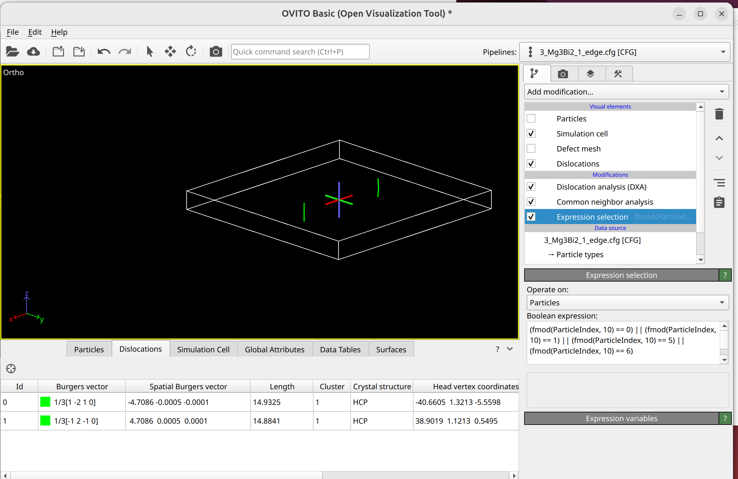
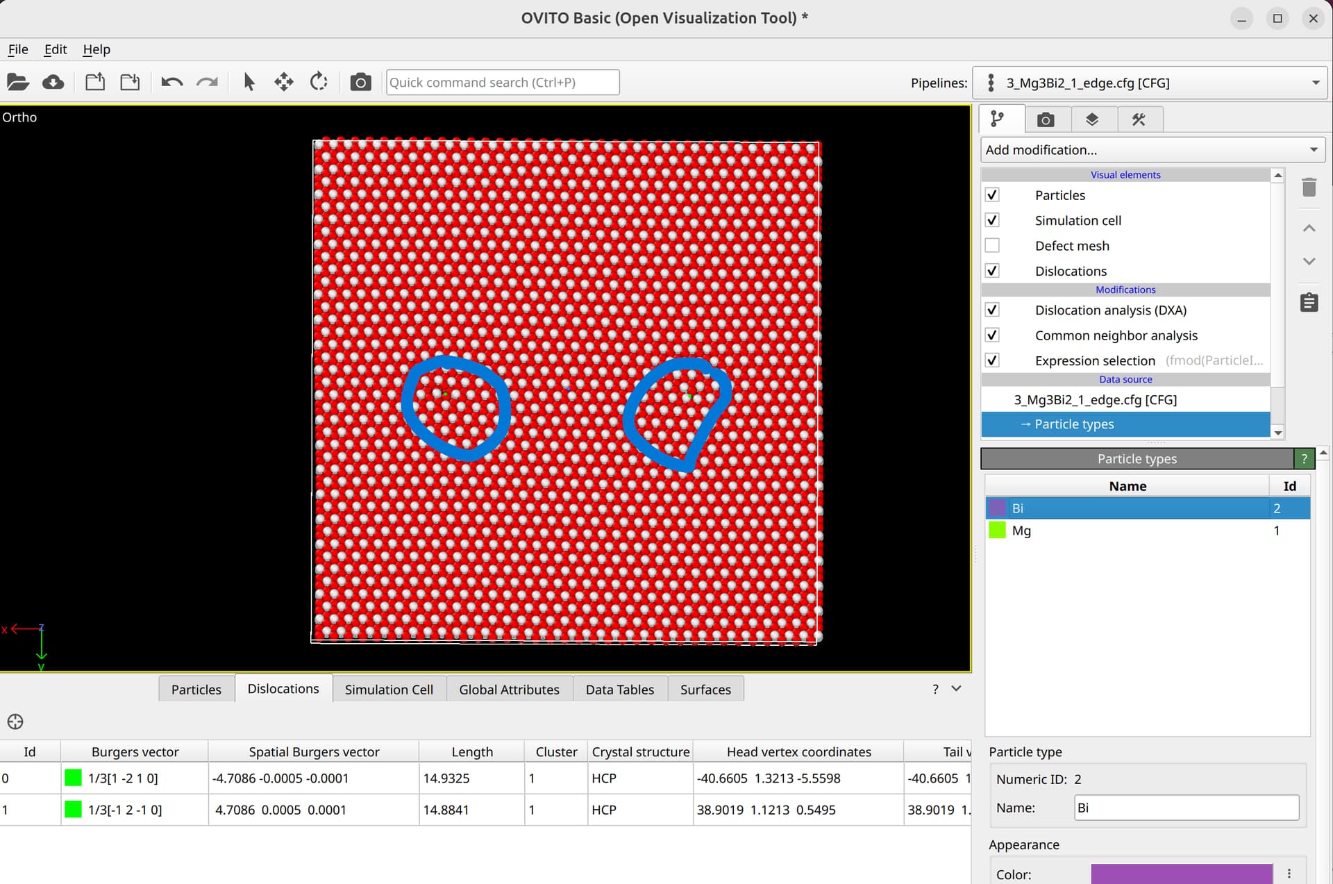
To select dislocation core atoms, you can use the “mark dislocation core atoms” setting in DXA. This will mark atoms that are part of the defective region identified as the dislocation core. You can select them using the expression selection modifier with the expression: Dislocation>=0. Note that this will only select atoms that are part of the existing selection used as input into DXA. Therefore, you have to use the expand selection modifier to select other atoms inside the unit cell that were not selected previously.

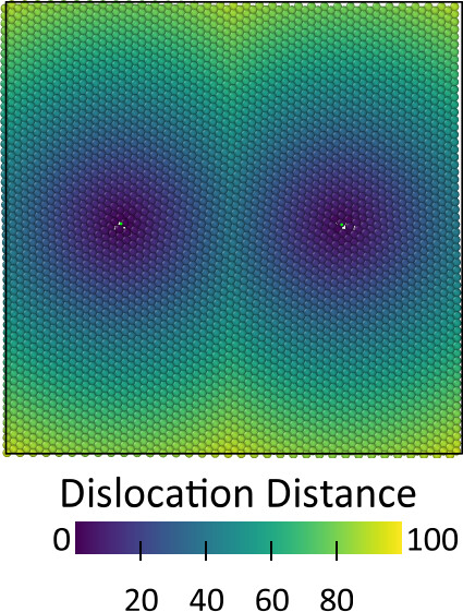
Alternatively, you can compute the distance for all atoms to the dislocation line using this code:

"""
Copyright (c) 2025 Daniel Utt

Permission is hereby granted, free of charge, to any person obtaining a copy of
this software and associated documentation files (the "Software"), to deal in
the Software without restriction, including without limitation the rights to
use, copy, modify, merge, publish, distribute, sublicense, and/or sell copies of
the Software, and to permit persons to whom the Software is furnished to do so,
subject to the following conditions:

The above copyright notice and this permission notice shall be included in all
copies or substantial portions of the Software.

THE SOFTWARE IS PROVIDED "AS IS", WITHOUT WARRANTY OF ANY KIND, EXPRESS OR
IMPLIED, INCLUDING BUT NOT LIMITED TO THE WARRANTIES OF MERCHANTABILITY, FITNESS
FOR A PARTICULAR PURPOSE AND NONINFRINGEMENT. IN NO EVENT SHALL THE AUTHORS OR
COPYRIGHT HOLDERS BE LIABLE FOR ANY CLAIM, DAMAGES OR OTHER LIABILITY, WHETHER
IN AN ACTION OF CONTRACT, TORT OR OTHERWISE, ARISING FROM, OUT OF OR IN
CONNECTION WITH THE SOFTWARE OR THE USE OR OTHER DEALINGS IN THE SOFTWARE.
"""

from ovito.data import DataCollection
from ovito.pipeline import ModifierInterface
import numpy as np


class DislocationDistanceModifier(ModifierInterface):

    @staticmethod
    def distance_points_to_segment_3d(points, seg_start, seg_end):
        """
        Calculate the minimum distance from multiple points to a line segment in 3D.

        Args:
            points: array-like of shape (n, 3) - array of points [(x1, y1, z1), (x2, y2, z2), ...]
            seg_start: tuple/array (x, y, z) - start point of line segment
            seg_end: tuple/array (x, y, z) - end point of line segment

        Returns:
            numpy array: distances from each point to the line segment
        """
        points = np.array(points)
        seg_start = np.array(seg_start)
        seg_end = np.array(seg_end)

        # Vector from seg_start to seg_end
        segment_vec = seg_end - seg_start

        # Handle degenerate case where segment is a point
        segment_length_sq = np.dot(segment_vec, segment_vec)
        if segment_length_sq == 0:
            return np.linalg.norm(points - seg_start, axis=1)

        # Calculate parameter t for each point
        # t represents where the projection falls on the line
        point_vecs = points - seg_start
        t = np.dot(point_vecs, segment_vec) / segment_length_sq

        # Clamp t to [0, 1] to stay within the segment
        t = np.clip(t, 0, 1)

        # Find the closest point on the segment for each input point
        closest_points = seg_start + t[:, np.newaxis] * segment_vec

        # Calculate distances
        distances = np.linalg.norm(points - closest_points, axis=1)

        return distances

    def modify(self, data: DataCollection, *, frame: int, **kwargs):
        # Get the positions of all particles
        positions = np.asarray(data.particles.positions)

        # Pre-allocate the array for storing the minimum distances
        dislocation_distances = np.ones(positions.shape[0]) * np.inf

        # Loop over dislocations
        for segment in data.dislocations.segments:
            # Loop over all dislocation line segments
            for i in range(1, len(segment.points)):
                # Compute the minimum distance from each particle to the current line segment
                distances = self.distance_points_to_segment_3d(
                    positions, segment.points[i - 1], segment.points[i]
                )
                # Update the minimum distance for each particle
                dislocation_distances = np.minimum(dislocation_distances, distances)

                yield i / len(segment.points)
        # Store distances in data object
        data.particles_.create_property(
            "Dislocation Distance", data=dislocation_distances
        )

Subsequently, the expression selection modifier can be used to select all atoms within a given distance from the dislocation as core atoms.

Thanks, I solved it.

Recently, I try to recognize the dislocations in different orientation systems of Mg3Bi2 based on the above method. But still some problems, thanks for your replying.

  1. Mg3Bi2, orientation is X=[1-210], Y=[0001], Z=[10-10], Burgers vector is [10-10]. I build partial dipole dislocation. But I can find only one dislocation, I can’t find another one in ovito, as shown Fig.1(3_Mg3Bi2_3_screw). If I increase the magnitude of Burgers vector, I can find dipole dislocation and ovito showed 1/3 [20-20], as shown Fig2 (4_Mg3Bi2_3_screw). How do I modify it that let the structure of Fig.1 show two dislocations in ovito.

3_Mg3Bi2_3_screw.xsf (857.7 KB)
4_Mg3Bi2_3_screw.xsf (857.7 KB)


  1. Mg3Bi2, orientation is X=[11-2-3], Y=[1-100], Z=[5 5 -10 6]. I can’t find dislocation in ovito.
    3_Mg3Bi2_2_edge.xsf (1.4 MB)

Thanks for your replying.

I checked your Mg3Bi2 file with orientations X=[11-2-3], Y=[1-100], Z=[5 5 -10 6] as an example. After deleting atoms based on the selection expression used before, the structure is not identified as HCP by Common Neighbor Analysis (CNA). Therefore, DXA cannot work, as it uses CNA internally as its first processing step.

You may need to adjust which indices are selected to identify the HCP backbone.

Thanks for your replying. I will select the indices again.

So the first system is orientation with X=[1-210], Y=[0001], Z=[10-10]. Why did it show only dislocation?

My recommendation would be to tag the atoms belonging to the HCP lattice in the initial unit cell, e.g., by renaming their type to “Mg_hcp” instead of “Mg”. This makes selecting them easier after you have inserted your defects and applied rotation. This is especially useful since edge dislocations inserted into the system usually delete atoms, making index-based deletion like you’re currently using cumbersome or impossible.

Thanks for your advice. :grinning: