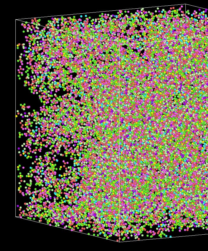
I have been using LAMMPS to run an NPT (constant Number of atoms, Pressure, and Temperature) simulation. The density of my system has reached 1.03, but visually, it still appears to have empty spaces. I’m curious about the possible reasons behind this observation. Below, I have included my input file and the output structure.
Input File:
dump 1 all custom 10000 dump/dump.atom.* id mol type mass q x y z vx vy vz fx fy fz
dump_modify 1 sort id
neighbor 2.5 bin
neigh_modify every 1 delay 0 check yes
minimize 1.0e-6 1.0e-6 1000 10000
timestep 1
thermo 10000
thermo_style custom step temp press vol epair emol etotal enthalpy density
thermo_modify format float %20.10g
velocity all create 393 1234567 rot yes dist gaussian
fix n1 all nvt temp 393 700 100
run 1000000
unfix n1
fix n1 all nvt temp 700 700 100
run 5000000
unfix n1
fix npt_name1 all npt temp 700 393 100 iso 200 200 1000 fixedpoint 0 0 0
run 30000000
unfix npt_name1
fix n2 all nvt temp 393 393 100
run 10000000
unfix n2
It’s a bit strange to ramp down the temperature during an NPT run, but beyond that – it’s impossible to even guess without knowing what you are modelling. LAMMPS is used to model metals, polymers, liquids, glasses, gases, and even how human mobility affects the spread of a pandemic. Why voids might emerge during NPT simulation will be very different for each of these different scenarios.
Thank you for your answer. The system I am referring to is a metal-organic framework (MOF). I have always assumed that a density of 1 would indicate a dense system. Lowering the temperature is done with the intention of returning to 393 K after raising it again.
A density of 1 is just a density of 1 … in whatever units you are using. Whether that is dense or not depends on the material being used. A sample of water with a density of 1 g/cm^3 would be just standard liquid water at room temperature and pressure. A sample of stainless steel with a density of 1 g/cm^3 would be exceptionally porous.
Anyway, aren’t MOFs usually supposed to be porous??
Thank you for your response. I want to use NPT simulation to make the distribution of molecules in my system more uniform. However, currently there are randomly occurring voids, which seem to be caused by molecular aggregation leading to voids in the neighboring positions.
Do you have bonded potentials modelling interactions in your system? I am asking cause there is no representation of bonds in the image you uploaded (but maybe you just chose to omit it). Also, are you sure you are inputting the potential parameters correctly?
I was thinking that maybe you damaged the structure during the npt part of the simulation and it was not able to recover once you moved forward to the nvt (by the way, it’s not a good idea to do an nvt after an npt since you have no control on what is the last value of instantaneous volume reached during the npt dynamics). Maybe you can save structural information (like rdfs) in order to follow the whereabouts of your system’s structure and get a better idea of what is happening in each stage of your simulation.
Also, like Shern, I dont understand why you are trying to get rid of “voids” since your system is supposed to be porous (right?). Is this something like an amorphous MOF?
If for some reason you want a density of 1, maybe you can try a different strategy for altering the volume of yoru simulation box accordingly (like the change box command and things like this).
Thank you for your response.
I apologize for using a dump file, which resulted in the missing key relationships in the image. I used UFF in the metal part. This is my first time calculating a hybrid organic-inorganic system. May I ask how you select the positional information for the metal?
The figure below represents a system with a density of 1.049. What confuses me is that it does not appear to be pores of a MOF material but rather blank areas caused by the aggregation of MOF on the other side.
How do you determine if the structural relaxation of your MOF material is reasonable when performing calculations? At what density does the system typically stabilize?
I couldn’t find experimental evidence in the literature, and the researchers didn’t provide me with an answer. In cases like this where there is no experimental reference, how can one determine density?
Well, if you have a crystalline MOF, you should be able to know the position of each atom (metal included) from the crystallographic structure. Where did you get your initial configuration to run the simulations from? Did you build it yourself from scratch? You can maybe find an initial configuration ready-to-go in databases or from some people that work with the same MOF as you and sometimes share it. Which MOF are you working with, if I may ask?
What did you use for the rest? UFF also? Note that the force-fields in UFF are general (i.e. work reasonably well to model interactions in many different systems) and the parametrization was not derived considering MOFs (if I remember correctly). I know that there is a UFF4MOF which has improved the UFF parametrization for specific interactions existing in different MOFs and should improve the overall structural results. Also, I remember I had to use UFF some time in the past and it was a pain in the ass to find the parametrization because, if I remember correctly, the paper has some typos and also some missing information that took me some time to find out from reliable sources. Where did you get your parameters for UFF? Did you use some software instead of trying to figure out from the original ublication? It could also be that the parameters you obtained are wrong. I will look back my notes in a few hours to see what were the problems I had in the original publication and how I managed to get the proper parametrization.
Yet, despite what I said about the force-field above, my guess is that your structure is messed up because you are forcing it to have a density of 1 (units unknown) arbitrarily. You cannot do that. Well, technically you can, but you would be simulating a thermodynamic state that will very much probably not be the desired one or maybe shouldnt even exist for the crystal phase of the MOF depending on how the phase diagram looks like. If you are unsure about the density (which I personally find very weird that you cannot find this reported literally anywhere), maybe it is better to do the dynamics in the NPT ensemble at ambient conditions (say T = 300K, p = 1 bar) and then figure out what is the corresponding density at that thermodynamic state. Note also that this is the density your force field is predicting and therefore may not match the not the real, observable density of the actual material in the real world.
EDIT:
If you are unsure about the density (which I personally find very weird that you cannot find this reported literally anywhere), maybe it is better to do the dynamics in the NPT ensemble at ambient conditions (say T = 300K, p = 1 bar) and then figure out what is the corresponding density at that thermodynamic state.
I am assuming you are studying your system at ambient conditions, but if not, you can do the NPT dynamics corresponding to whatever thermodynamic state you are interested at studying.
So, for what is worth, in case it helps you in anything, I have the following notes in my “simulation diary” from when I used UFF force-fields in the past:
" The implementation of the UFF was carefully made in non-automated (handmade) fashion from the original publication taking into consideration the cautions proposed by Marcus Martin [ref4] and highlighted in the manual of lammps-interface [ref6]. The values of GMP electronegativities of the different atom types, necessary for the parametrization, were taken from the database of lammps interface, available in the github repository [ref5]. // The Coulombic interactions were considered with the dielectric constant of 1, as praised in the UFF setup guidelines. The charges however were not derived using the adviced QEq charge equilibration scheme cited in the official UFF publication being, instead, taken from existing classical models for the MOF and the polymer found in the literature, in which partial charges were derived from different DFT methods [ref7], [ref8]"