[lammps-users] using the solid liquid interface to calculate melting point of LiAlO2

Hello,
I am using the solid liquid interface method to calculate the melting point of LiAlO2 (melting temperature is roughly 2000K). I am taking a long cuboidal simulation cell of LiAlO2 and melting a small slab section in the middle of the long box to 6000 K while the rest of the box is at 1800 K. My hypothesis is that the solid liquid interface (SLI) SLI1 and SLI2 should move closer to each other with time as the rest of the box is at 1800 K which is below the melting point of LiAlO2 (MP is 2000K). size of box: 31 X 31 X 113 angstrom
Potential used: core shell potential from "

“Atomistic simulations of the defect chemistry and self-diffusion of Li-ion in LiAlO2.” Energies 12, no. 15 (2019): 2895.

density and structure are correctly reproduced from these potentials.

The inputs and output are given below

Z direction --------->


SLI1 | SLI2 | |
solid | liquid | solid |
1800 K | 6000K | 1800K |

| |____________ |

The code is given below:

units metal
dimension 3
boundary p p p
atom_style full

fix csinfo all property/atom i_CSID
read_data largecell22.lmp fix csinfo NULL CS-Info

group cores type 1 2 3
group shells type 4

variable z14 equal 0.40zhi+0.60zlo
variable z34 equal 0.60zhi+0.25zlo
region midregion block INF INF INF INF {z14} {z34}
group midgroup region midregion
fix zeromomentum all momentum 1 linear 1 1 1

variable myT equal 1800
velocity all create ${myT} 87287
velocity all zero linear

pair_style buck/coul/long/cs 10 12
pair_coeff * * 0.0 1.000 0.00
pair_coeff 1 4 632.1018 0.2906 0.00 #Li core O shell
pair_coeff 2 4 1109.92381 0.31540 0.00 #Al core O shell
pair_coeff 4 4 12420.5 0.2215 29.07 #O shell O shell

bond_style harmonic
bond_coeff 1 31.0 0.0

kspace_style ewald 2.0e-3

neighbor 1.0 bin
neigh_modify every 20 delay 0 check no

variable time equal step*dt

thermo 100
thermo_style custom step v_time temp pe ke etotal vol press

thermo_modify norm no

initially heat up to ${myT} K, will be reached after about 10 ps with nosehoover npt

to get the correct volume

fix 1 all npt temp {myT} {myT} 0.1 aniso 0.0 0.0 0.1
#dump dump1 all custom 1000 dump.therm.gz id type x y z
#dump_modify dump1 sort id
timestep 1.0e-3
run 10000
#write_restart restart.therm
#undump dump1
unfix 1

over melt the mid with berendsen 50 ps

#dump dump1 all custom 1000 dump.overmeltmid.gz id type x y z
#dump_modify dump1 sort id
reset_timestep 0
fix 1 midgroup nve
fix 2 midgroup temp/berendsen 6000.0 6000.0 0.1
run 50000
#write_restart restart.overmeltmid
#undump dump1
unfix 1
unfix 2

compute K all ke/atom
variable keeV atom “c_K * 0.043364102”

velocity midgroup create {myT} 87287 velocity all zero linear dump dump1 all custom 1 dump.melt.gz id type x y z vx vy vz fx fy fz v_keeV dump_modify dump1 sort id reset_timestep 0 fix 1 all nve fix 2 all temp/berendsen {myT} ${myT} 0.1
run 250000
#write_restart restart.melt
undump dump1
unfix 1
unfix 2

Output:

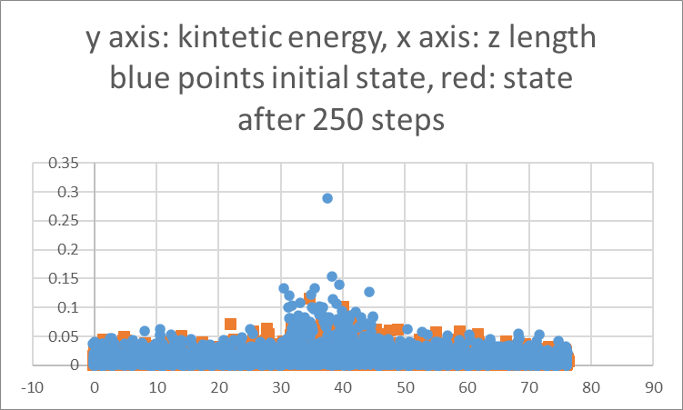
I am plotting the kinetic energy (representative of temperature) vs z coordinates at 2 time instances, First at the beginning of the simulation and second after 250 steps. My time step is 0.001 ps. I expect to see the peak of the kinetic energy to become narrower signifying that the SLIs are moving closer to each other. But instead I am seeing that peaks flattens and broadens.

Question 1: Is my approach correct? Is there a better way to quantitatively track the movement of solid liquid interface?

Question 2: If I raise the temperatures of the side sections to 2500K can I expect the SLIs to move away from each other?
The observation for T= 2500K is shown below.
I am not able to see the SLIs move away because the red peak is not becoming wider. Is my hypothesis wrong?
Why are there high energy points at the boundaries in both initial and final states?

Sincerely,
Ankit

Hi Ankit,

Some things that come to mind:

Do you need a temp/cs compute to correctly calculate the temperature of the core shell system, especially for use with thermostatting?

You have defined “midgroup” at the beginning of your script, which means that the group will consist of particles which were in that region at the time when you defined the group. As particles diffuse over time the “midgroup” particles will move throughout the box. You need to define a dynamic group for what you have in mind (see documentation for details). I can’t predict if this will work well with temp/cs.

Is there a reason you’re using Ewald instead of PPPM for the long range solver, and using it at such low accuracy as well? I would expect you need at least 1e-4 accuracy.

Cheers,
Shern

Have you looked up any papers or textbooks discussing how to determine a melting point with coexistence simulations.
What you describe sounds very different. The way I remember it is something along these lines:

  • create a sufficiently large bulk crystal and equilibrate it while solid to the expected melting point temperature. due to melting being an activated process it will remain solid. otherwise your estimate may be way off and the force field not suitable.
  • define a region that is half the bulk system and now time integrate only those atoms (the remaining atoms are unchanged). heat this subsystem to a much higher temperature so that it melts and run it at high temperature long enough so that it is well in the liquid phase and has no remaining “structural memory” of the crystal geometry.
  • quench that subsystem and equilibrate it to the same temperature than you have the solid half equilibrated to
  • add one or more computes that record local order so that you can follow which atoms are liquid and which are solid. which compute is best suited for this depends on your system in the solid phase. it doesn’t hurt to try multiple at the same time to have confidence in your observations.
  • equilibrate for a little bit more and possibly adjust the box length a little bit in the direction of the phase transition and keep a restart of that prepared system
  • now do a series of simulations with temperatures higher or lower as as the expected melting point and observe whether the solid or the liquid phase part grows
  • keep iterating and running different temperatures (most efficient is some bisectioning scheme) until you find the temperature where the two phases remain of steady size

you are diverging in core steps and thus your approach is not at all comparable.

  • kinetic energy is not a very sensitive property to look at in the first place and if you are doing a coexistence simulation the kinetic energy should be the same in all regions. this is crucial
  • there are multiple choices in your input that would create problems and doubt in the reliability and correctness if your simulation even if it was only to study the plain solid or liquid bulk system
  • your long-range coulomb handling is completely insufficient
  • the choice of a berensen thermostat is not a good one for this kind of system and setup. for heating/quenching you should be better off with a dissipative thermostat and not a scaling thermostat and for production you should have weak coupling like with a nose-hoover thermostat
  • there should be no need for using fix momentum in a partially solid system. if you see a center of mass drift, then it is likely due to causes that should be investigated and properly eliminated instead of suppressed
  • your choice of neighbor list settings is too aggressive for the chosen time step.
  • since you are using a core-shell model, have you checked that your choice of timestep is suitable for proper energy conservation for a plain bulk (solid) system near the melting point?
  • there are multiple computes that track local order, which is most suitable only you can figure out by testing them.

at this point, things are getting repetitive and you have to make a choice: either you follow the advice given closely or you do as you feel. however, don’t expect that people will be eager to answer any further questions about why your simulation is not working as expected or not giving you the expected results. also, what you are doing is an “advanced” method (and you are using an “advanced” force field, too. so you need to be more careful and check the correctness of your simulations in smaller steps and overall approach the “production” simulation in smaller increments. it will be difficult to give any more specific advice beyond what you already have been given since that would require to first go and complete the same simulation study for the same system. I don’t have the time and interest to do that. If anything, this would be something you need to work on with your adviser/supervisor or somebody that has interest in tutoring you personally.

Thank you Dr. Kohlmeyer and Dr. Tee for your inputs.
Dr. Kohlmeyer,Thank you for that elaborate description of the method. I compared my method with yours and I think I am along the similar lines as to what you described. Initially I am heating the whole simulation box to slightly below the expected melting point, then heating the mid section (shown in the figure below) to 6000K and then equilibrating the whole box to the same temperature as that of the solid half. Now my anticipation is that if the liquid phase grows in volume, the solid-liquid interface will move apart. I am tracking the kinetic energy of these regions as I think the Kinteic energy is the signature of the temperature. If the liquid region expands, the solid-liquid interface will move away from each other.

Z direction --------->


SLI1 | SLI2 | |
solid | liquid | solid |
1800 K | 6000K | 1800K |

| |____________ |

However I don’t see clearly the expansion of the high kinetic energy zone after 0.25 ps as. The blue and red dots are the Kinetic energy of particles at t=0 and t=0.25 ps respectively, during the quenching of the subsytem to the same temperature as the solid zone.

The code was attached in the previous email. Am I wrong in this method?
Also what compute should I use to track the local order? Should I use RDF only on the middle section which is being quenched from liquid to solid?