Hello Everyone
I’m trying to model a geometry that consists of two cylinders and a box that will pass between them. I created the cylinders using the fix rigid command and only allowed the torque in the y-axis (desired rotation axis). When the box starts to move towards gap between the rollers (using fix move) the atoms overlap (I only excluded the interactions inside the cylinder itself). A video showing the process is available at the bottom of the page: https://link.springer.com/article/10.1007%2Fs11837-019-03699-y#Sec5
As the upper walls of the box come close to the rollers there is a repulsive force (from rollers to box). How can I induce such force, I tried using wall commands but they seem to work only for flat walls and not whole regions. Kindly advise on how to prevent the overlapping of atoms between the box and the rollers.
Regards
The problem seems to me to be the use of fix move. Atoms that are controlled by fix move will move without any regard for forces. That is how fix move works.
Axel.
Thank you for your advice
I’ve been trying several methods in the past week. LJ walls, and optimized pairwise interactions between the rollers and the box that passes between it. In that paper it was mentioned that the rollers exert a compressive force in the box. Is there is a way to generate a “force field” from the rollers not by pairwise interactions ? I cannot find anything related in the manual page of the Fix rigid command.
When I tried the optimized LJ parameters method, the material was bent but it returned back to original thickness.
Thank you in advance
Thank you for your advice
I've been trying several methods in the past week. LJ walls, and optimized pairwise interactions between the rollers and the box that passes between it. In that paper it was mentioned that the rollers exert a compressive force in the box. Is there is a way to generate a "force field" from the rollers not by pairwise interactions ? I cannot find anything related in the manual page of the Fix rigid command.
these are really more conceptual questions than LAMMPS questions.
you are doing classical *atomic* MD simulations. so interactions are
expected to be modeled by modeling interactions between atoms and
following the laws of (classical) newtonian physics. already using fix
rigid is a significant deviation, since materials are usually *not*
rigid. rather they have different compressibilities and different
levels of elasticity.
When I tried the optimized LJ parameters method, the material was bent but it returned back to original thickness.
if you are still in the regime of elastic deformation, that is what I
would expect.
in general, it looks like you need to decide whether you want to do a
physical model (where particles move according to physics) or a
computer animation (where particles move the way you want them to
move). sometimes those two can be the same, but that is a question
both the expectations and the physics, not a matter of what LAMMPS
does.
axel.
to add to my previous response, i would expect a more physical model
for what you describe to be constructed from having only a part of the
system driven by fix move or fix rigid:
some visualization are here:
https://www.youtube.com/watch?v=3cWXG7gBgME
only the green atoms are rotated the red atoms can move freely (via fix nve)
and here:
https://www.youtube.com/watch?v=-JpgiXyc8o8
only the blue atoms are rotated (again with fix move) and the red
atoms are a different material attached to the green atoms via
pairwise interactions only.
axel.
Thank you for your advices and links, I actually came across them when I was trying to model the rollers.
The model purpose is to perform cold rolling on a sample. The rigid bodies are just a way for modelling non-deformable rollers to generate the effect of the complex forces associated with the rolling process. In the animation link in my first email there is a gap between the rigid rollers and the body being deformed. Therefore, I predicted that there must be a force field between the rigid rollers and the body that causes permanent deformation which the author claims to be due to the interatomic potential. However, the force is always repulsive and no atoms are being attracted to the rollers. This means that the pairwise interactions do not exist or was manipulated somehow. That is the reason I asked if there is a way to generate stress tensors outwards from rigid bodies. On the other hand, the fix move is used to move the simulation box through the rollers.
Another method I tried was to use the LJ potential to model interactions between the rollers and the body (with optimized LJ parameters to generate a specific force) but the method did not because the bodies return back to original thickness. I performed up to 80% reduction on Fe , that is outside the elastic regime.
FYI,
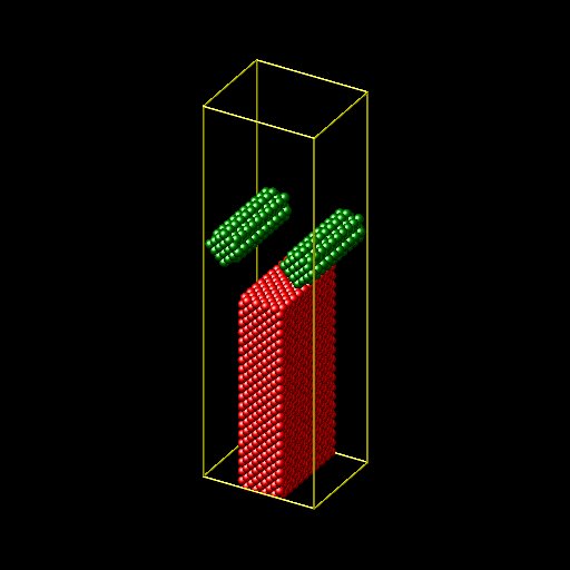
I just did a very crude and minimal/small approximation of what you
describe that you are modeling.
- just used a single material (metal) and make the "rollers"
incompressible by not letting them move at all
- i use fix addforce to drive the workpiece through the "rollers".
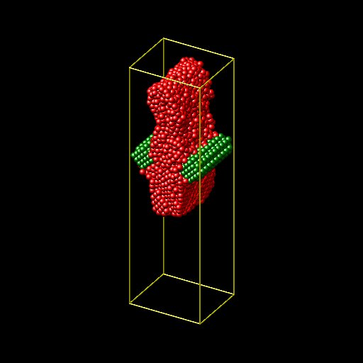
as you can see from the two images, there is definitely some plastic
deformation happening.
for a physical more meaningful model i would:
- do everything larger (i made it small so it can run quickly because
this is for demonstration purposes only)
- use a different, harder material for the rollers than for the
workpiece and have all but a few particles to drive the mechanics move
freely with fix nve.
- impose a rotation of the rollers by selecting a few random particles
in the core and moving them with fix move when the rest is propagated
with fix nve
- impose the fixed speed translation on the workpiece in the same way
by picking a few random atoms in the center of the slab
- use realistic speeds/forces. in the demo the driving force is rather
large to make it run fast.
the "demo" script:
units metal
lattice fcc 3.52
boundary p p p
region box block -5 5 -6 6 -20 20
create_box 2 box
region workpiece block -5 5 -2 2 -20 0
create_atoms 1 region workpiece
group workpiece type 1
region rod1 cylinder x -4.0 5 1.55 -5 5
region rod2 cylinder x 4.0 5 1.55 -5 5
create_atoms 2 region rod1
create_atoms 2 region rod2
pair_style eam
pair_coeff * * Ni_u3.eam
run 0
write_dump all image init.jpg type type zoom 1.5 adiam 3.5
velocity workpiece create 300 23562345
fix 1 workpiece addforce 0.0 0.0 0.01
fix 2 workpiece nve
thermo 100
dump 1 all movie 100 push.mkv type type zoom 1.5 adiam 3.5
run 10000
write_dump all image end.jpg type type zoom 1.5 adiam 3.5