I am using the June 23, 2022 version of LAMMPS. I am currently studying substrate rotation and have applied the “rotate region” command to each region, as shown below.
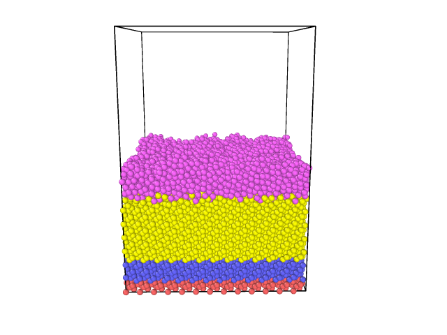
When I add the rotation component to the three substrate regions, some atoms of the substrate vanish. The image shows the situation without rotation, the other with substrate rotation.
Impossible to say since you are not providing sufficient information about what you are doing and why and which commands you are using. Nobody here can read your mind (of that of your computer) and thus knows anything specific about what you are doing.
You have been reminded to provide more details before, and it will happen again unless you change your ways (or you will be ignored once people get tired of reminding you). The best way to proceed in your situation with a command not behaving as expected is to construct a minimal input deck, that just reproduces the issue at hand, but does not contain any other commands beyond what is needed. It should also create a tiny system, so it can run fast. If you also explain what you want to achieve by using the specific command in question the way you are using it, you give people a chance to reproduce what you see and determine whether this is documented (and thus intended) behavior or an issue that needs to be corrected.
Okay, thanks.
My question concerns the rotation of the substrate during each 16.90 ps. Since there are three different regions in the substrate, I added the part (rotate v_theta 17.5 17.5 0 0 0 1) to each of the region commands. With the variable theta equal to 16.90 ps,
I used a single variable for each of the three regions. The coordinates (17.5, 17.5, 0) indicate the origin of the rotation axis, and coordinates (0, 0, 1) define the rotation axis parallel to the Z direction.
The following script demonstrates the program I employed to rotate the substrate.
units metal
dimension 3
atom_style atomic
boundary p p f
region box block 0 70 0 70 0 100 units box
create_box 2 box
variable theta equal 16.90
lattice diamond 5.431
region r1 block 0 70 0 70 0 2 units box rotate v_theta 17.5 17.5 0 0 0 1
create_atoms 1 region r1
group g1 region r1
fix 1 g1 addforce 0 0 0 region r1
mass 1 28.0855 # Si
mass 2 63.546 # Cu
region r2 block 0 70 0 70 2 16 units box rotate v_theta 17.5 17.5 0 0 0 1
create_atoms 1 region r2
group g2 region r2
fix 2 g2 nvt temp 300.0 300.0 $(100.0*dt)
region mobile block 0 70 0 70 16 40 units box rotate v_theta 17.5 17.5 0 0 0 1
create_atoms 1 region mobile
group mobile region mobile
fix 3 mobile nvt temp 300.0 300.0 $(100.0*dt)
fix 4 mobile nve
pair_style tersoff
pair_coeff * * Si.tersoff Si NULL
pair_style eam
pair_coeff * * Cu.eam
pair_style tersoff
pair_coeff * * SiCu.tersoff Si Cu
neigh_modify delay 0
region slab block 0 70 0 70 90 100 units box # le région de dépôt
group addatoms type 2
fix 5 addatoms nve
delete_atoms overlap 0.1 all all
compute add addatoms temp
compute_modify add dynamic/dof yes extra/dof 0
I see no command causing a rotation of a substrate anywhere.
The rotate option to the region will indeed rotate the region, but nothing else.
Your input looks to me like something that is just made up by somebody that thinks a computer program can “reason like a human” and thus can infer your intentions from the commands. But it is the other way around, you have to “think like a computer” instead and take each command at face value and assume only what the command’s description explicitly states.
This is most easily done by examining and checking an input step by step and verify each step individually for what it does. So, let’s review your input in pieces:
This will create an empty simulation cell of 70x70x100 angstrom with metal units and periodic boundaries in x- and y- direction and fixed boundaries in z.
This defines the variable theta as an equal style variable with a constant value of 16.90.
This changes the lattice setting to a diamond lattice with lattice spacing 5.431. So when using the default of “units lattice” for all commands that support the units keyword, the length increment will now be 5.431 instead of 1.0.
Now you are defining a rectangular region of 70x70x2 angstrom at the bottom of the box and then rotates it around the z axis with origin 17.5 17.5 0.0 and rotate it by 16.90 radians, i.e. approx. 968.3 degrees = 248.3 degrees. Since the origin is not in the center (35.0 35.0) or the xy plane and the angle is not a multiple of 90 degrees
This fills a region that is the intersection between the box and the rotated region.
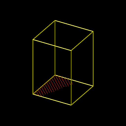
Inserting the command
write_dump all image g1.png type type
Creates a visualization of those atoms and the result seems reasonable:
This command adds a zero force to all atoms that are at the same time in the group g1 and in the r1 region, but adding a zero force has no effect, so the command is useless.
This sets the per-type masses
Now you create more type 1 atoms in a block above the first group/region, also with same rotation and axis, so they will occupy the same xy-area subset of the cell. For those you apply time integration with a nose-hoover thermostat targeting 300 kelvin.
And another group of type 1 atoms on top of the other group with the same region setting and also nvt time integration for the same temperature.
Up to this point, the system is exactly as the commands have determined it to be and LAMMPS has done exactly what you have asked it to do. It is not LAMMPS’ problem that the resulting system looks like you have shown, You have asked LAMMPS to create that system. This is sometimes referred to as the GI-GO principle, aka the “garbage-in, garbage-out” principle. In other words, if you have not thought out your input well, don’t be surprised that you don’t get the output you expect. If you want to see something else, you have to formulate your input accordingly.
Now you are adding another time integration fix to the last group, but this time without a thermostat. This is incorrect and LAMMPS will warn you about integrating atoms multiple times. You should have seen that warning (and take it seriously) in your output.
This part of the input makes very little sense. The first two pair_style and pair_coeff have no effect on the simulation at all, since the third pair_style and pair_coeff commands will wipe out all previous settings. Why not just use one of each?
Now you are defining another region but without creating any atoms and thus the group addatoms will be empty. To that empty group, you add plain time integration without a thermostat.
The first line creates a custom temperature compute for the (still empty) group and the second command tells it to check the temperature dynamically during the run disregarding translation invariance.
This utilizes fix deposit to add atoms to the (previously empty) group using the empty region with a fixed verlocity in x and z direction but none in y. So the atoms should move through the vaccuum in a diagonal motion at a 45 degree angle with respect to x and 90 degree angle with respect to y.
This puts a reflecting wall at the top of the box.
This sets up thermodynamic output and tells it to use the temperature of the deposited atoms as temperature output.
This runs an MD of the system for 200ps with a 1fs timestep.
This removes the deposit fix
This adds a second time integration to the g2 group with a very long relaxation constant of 100ps. Same as for the case of the “mobile” group, this is incorrect and LAMMPS will warn about it.
Now you run MD for another 20ps, which makes the choice of a 100ps time relaxation value for the fix-ID 9 command particularly meaningless.
In summary, the simulation has major flaws which makes its results bogus, even if you would be using it without the rotated regions.
It is not at all clear what you want to achieve by rotating the regions, it makes no sense from my point of view. I’ve seen inputs like this many times before from people that have no proper training in performing MD simulations and that hope that when they just use some command or settings that somehow sound similar enough as if they might do something akin to what is intended to do and the software will somehow sort it out and they don’t have to go through all the hard steps of learning how to set up such simulations (baby) step by step and under the tutelage of a sufficiently experienced adviser/mentor/tutor. However, this guaranteed to no work out. There are simply too many permutations of combination of commands to hit a correct combination just by chance. Please keep in mind, that even a simulation that completes without error, and looks reasonable, may still produce bogus results.