Hello all,
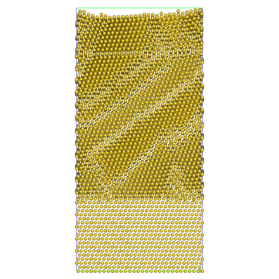
I am trying to calculate the stacking fault energy of the a copper sample. I have tried to calculate the stacking faults with unrelaxed and relaxed surfaces sliding along the [1 1 -2] direction for 111 Cu face. When I run with the unrelaxed surface, I get a reasonable value of 34 mJ/m^2 (The stacking fault energy is calculated as the difference between the energy of the unperturbed surface and the deformed surface divided by the surface area of the stacking fault, which is 18 lattice units in each x and y direction times the 3.615 Angstrom lattice cell length in each direction). I also get a smooth curve that shows the maxima in unstable stacking fault energy prior to reaching the minima for the stacking fault energy. However, when I try to allow relaxation parallel to the [111] direction in the surface, the stacking fault energies have no pattern to the values (This is shown in the attached graph). Below I have included the script I used for calculating the stacking fault energy. The changes in the dy variable were made through the command line call to the program, which is executed recursively from a shell script. The only difference between the two scripts is that unrelaxed stacking fault energies did not include the minimization commands, while the relaxed stacking fault energies did include the minimization commands. Does anyone have any thoughts or help as to why the relaxed stacking fault energy calculations are resulting in such differences?
Thanks,
Ken
INPUT SCRIPT****************
Find the stacking fault energy of a fcc metal
echo log
units metal
dimension 3
boundary p p s
atom_style atomic
variable cell_len equal 3.615
#variable dy equal 0.10
lattice fcc 3.615
region box block 0 18 0 18 0 36 units lattice
create_box 1 box
lattice fcc 3.615 orient x 1 -1 0 orient y 1 1 -2 orient z 1 1 1
create_atoms 1 box
region boundary1 block INF INF INF INF 30 INF
region boundary2 block INF INF INF INF INF 6
group boundary1 region boundary1
group boundary2 region boundary2
group boundary union boundary1 boundary2
group remainder subtract all boundary
region fault block INF INF INF INF 17.95 INF units lattice
group fault region fault
displace_atoms fault move 0 ${dy} 0 units lattice
pair_style eam/alloy/opt
pair_coeff * * Cu01.eam.alloy Cu
neighbor 2.0 bin
neigh_modify every 5 delay 0 check yes page 10000000 one 200000
compute potenga all pe/atom
compute sum_potenga all reduce sum c_potenga
fix noforce boundary setforce 0 0 0
fix nolatforce remainder setforce 0 0 NULL
reset_timestep 0
thermo 10
thermo_style custom step etotal pe ke lx ly lz press pxx pyy pzz c_sum_potenga
#***** Minimize commands used for relaxed stacking fault energy only *****
min_style cg
minimize 1.0e-20 1.0e-10 10000 100000
run 0
variable aeng equal c_sum_potenga
variable xlen equal lx
variable ylen equal ly
print “Surface Energies: {dy} {aeng} {xlen} {ylen}”