Hi all — I need help diagnosing a problem with a LAMMPS simulation of an amorphous silicon (a-Si) nanobeam under bending.
What I’m doing:
I used an LAMMPS workflow that worked fine for crystalline, isotropic Si. To get an amorphous beam I:
- Created a small periodic amorphous Si block (a-Si seed) by melting a diamond lattice and quenching, then wrote the result to aSi_tile.data:
# Create a small periodic amorphous silicon block (a-Si seed)
# Units: metal | Potential: Stillinger–Weber | Lattice: diamond

variable       S    equal    4

units           metal
dimension       3
atom_style      atomic
boundary        p p p

# 1. Create crystalline Si seed
lattice         diamond 5.43

region box block 0 ${S} 0 ${S} 0 ${S} units lattice
create_box 1 box
create_atoms 1 region box
mass 1 28.0855

# 2. Define potential
pair_style      sw
pair_coeff      * * Si.sw Si

neighbor        2.0 bin
neigh_modify    delay 10 check yes

# 3. Initialize
timestep        0.001       # 1 fs
velocity        all create 300.0 12345 mom yes rot yes dist gaussian

thermo          1000
thermo_style    custom step temp press pe etotal vol

# 4. Melt crystalline Si
fix             melt all npt temp 300.0 3500.0 0.1 iso 0.0 0.0 1.0
dump            001 all custom 1000 melt.xyz id type x y z
run             50000        # 50 ps
unfix           melt
undump          001

# 5. Quench to amorphous
fix             quench all npt temp 3500.0 300.0 0.1 iso 0.0 0.0 1.0
dump            002 all custom 1000 Quench.xyz id type x y z
run             100000       # 100 ps
unfix           quench
undump          002

# 6. Relax at room temperature
fix             relax all npt temp 300.0 300.0 0.1 iso 0.0 0.0 1.0
dump            003 all custom 1000 relax.xyz id type x y z
run             20000        # 20 ps
unfix           relax
undump          003

# 7. Output periodic amorphous block
write_data      aSi_tile.data          # will be used for replication
dump            1 all custom 200 dump_aSi_tile.lammpstrj id type x y z
- Read aSi_tile.data into a second script, replicated it along x to make the beam, set fixed and mobile end regions, equilibrated, then bent the beam by moving the mobile end with fix move:
# LAMMPS script for bending of a silicon nanobeam using fix move

variable   S         equal    4                # Length scale
variable velmob0    equal    0.001
variable velmob     equal (-1)*${velmob0}*${S}

variable iterequi   equal 100000
variable iterrun    equal 5300000

variable T equal 300
variable dt equal 0.001
timestep ${dt}

variable latconst equal 5.431

# Define nanobeam dimensions
variable XNW equal 10*${S}*${latconst}
variable YNW equal 1*${S}*${latconst}
variable ZNW equal 1*${S}*${latconst}

variable L_fixed  equal 0.1*${XNW}
variable L_mobile equal 0.15*${XNW}
variable XEdge    equal ${XNW}+v_L_fixed+v_L_mobile

units           metal
atom_style      atomic
dimension       3
boundary        s s s

# Read a-Si tile and replicate
read_data       aSi_tile.data
replicate       12 1 1         # 12× along x-axis (beam length)

# Define regions and groups
region fixed  block 0 ${L_fixed} 0 ${YNW} 0 ${ZNW} units box
group  fixed  region fixed

variable limX1 equal ${XEdge}-v_L_mobile
region mobile block ${limX1} ${XEdge} 0 ${YNW} 0 ${ZNW} units box
group  mobile region mobile

group  middle subtract all fixed mobile

set region fixed  type 2
set region mobile type 3

dump 009 all custom 1 initial.xyz id type x y z
run 1
undump 009

# Potential
pair_style sw
pair_coeff * * Si.sw Si Si Si

# Minimize and equilibrate
min_style cg
minimize 1.0e-6 1.0e-6 1000 10000

velocity all create ${T} 48284121 mom yes rot yes
fix 1 all nvt temp ${T} ${T} $(100.0*dt)

# Computes...
compute FXeqATOM all property/atom fx
compute FXeq all reduce sum c_FXeqATOM
compute FYeqATOM all property/atom fy
compute FYeq all reduce sum c_FYeqATOM
compute FZeqATOM all property/atom fz
compute FZeq all reduce sum c_FZeqATOM

dump 000 all custom 20000 dumpequilibration.xyz id type x y z
thermo 1000
thermo_style custom step temp pe ke etotal c_FXeq c_FYeq c_FZeq

run ${iterequi}
unfix 1
undump 000

# Production: apply bending
reset_timestep 0
fix 5 middle nvt temp ${T} ${T} $(100.0*dt)
fix 2 fixed move linear 0 0 0 units box
fix 4 mobile move linear 0 ${velmob} 0 units box
variable disp equal (-1)*step*${dt}*${velmob}

compute peatom  middle pe/atom
compute potential middle reduce sum c_peatom
compute keatom  middle ke/atom
compute kinetic middle reduce sum c_keatom

compute FYAtom1 fixed property/atom fy
compute FYfixed  fixed reduce sum c_FYAtom1
compute FYAtom2 mobile property/atom fy
compute FYMobile mobile reduce sum c_FYAtom2

compute mystress all stress/atom NULL virial
compute myTemp middle temp

fix result all ave/time 1 10000 10000 c_myTemp c_potential c_kinetic v_disp c_FYfixed c_FYMobile

thermo 10000
thermo_style custom step f_result[1] f_result[2] f_result[3] f_result[4] f_result[5] f_result[6]

dump 2 all custom 500000 dumpFast.lammpstrj id type xs ys zs c_mystress[1] c_mystress[2] c_mystress[3]
log logFigure.txt

run ${iterrun}
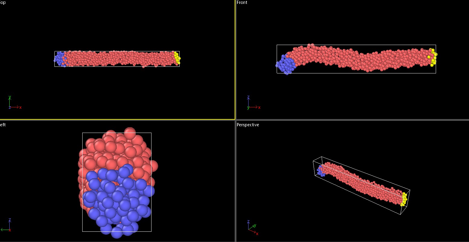
Problem:
Right after the equilibration step (the initial long run), the straight nanobeam spontaneously deforms into a weird shape before I start the bending run. This deformation happens immediately after equilibration and corrupts my bending results.
I would appreciate any hints or help identifying the likely causes. Thanks!