dimension 3
atom_style bond
units si
newton on
boundary f f f
region simulation_box block -0.01 0.01 -0.01 0.01 -0.01 0.01
create_box 1 simulation_box
variable rot equal PI/4
region reg block -0.002 0.002 -0.002 0.002 -0.002 0.002 &
rotate v_rot 0 0 0 0 1 0
lattice fcc 2e-4
create_atoms 1 region reg
dump 1 all atom 1 test.dump
mass * 1
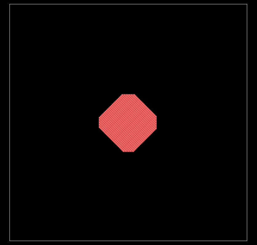
run 0
This is caused by the translate and rotate options for regions being added at a later point.
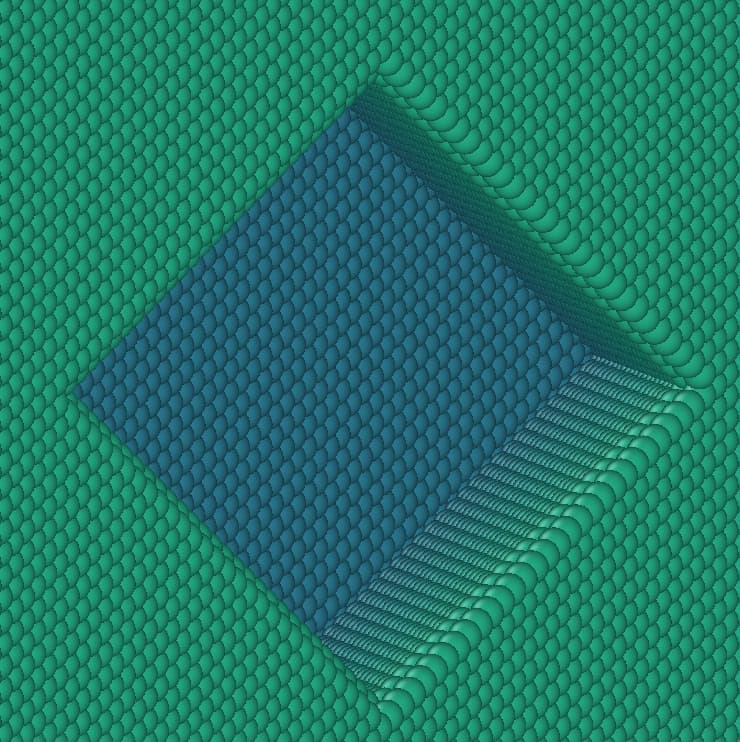
This was primarily for use with fix wall/region. The create_atoms command uses an optimization where the possible lattice sites for creating atoms are restricted by a bounding box for the region. This bounding box information is not updated when you rotate the region and hence you get the truncated corners, since you are essentially using an intersection of the unrotated region and the rotated region. The delete_atoms command does not benefit from the same optimization and thus it works as expected.
As in the post you are linking to a simple workaround is to not rotate the region but to displace the created atoms accordingly.
@jasmine969 For what it’s worth, instead of applying the code fix, another workaround is to use your full box creation method in the opposite way by deleting the atoms on the outside of your region by using the side option:
region      reg block -0.002 0.002 -0.002 0.002 -0.002 0.002 rotate v_rot 0 0 0 0 1 0 side out
lattice     fcc 2e-4
create_atoms 1 box
delete_atoms region reg
Thank you for quick replies. I also want to know how to fix deposit in this rotated region. The doc of fix deposit says that the region cannot be dynamic, disabling me to deposit in it now. But as you see, the rotation angle is a constant which does not change with time. So this rotated region is actually static. A dynamic group can be turned into static use group static. Can we also turn a dynamic region into static similarly, or create a static rotated region from scratch using something like region ID style args rotate/static theta Px Py Pz Rx Ry Rz? This will also save computation time of rotation at each time step.
By using a variable it is potentially dynamic. You cannot make a variable a constant. A static region is generated from primitives without transformations only.
No. If it was possible, it would be described in the documentation.
This computation is negligible.
In your specific case, you could emulate the shape of region you are looking for by using an intersection of 6 plane style regions.
On second thought, it will not work with fix deposit which requires a region with bounding box and that is not the case for plane regions and thus intersections of those regions.
Though it is feasible in this case, it may be not in others, e.g., a rotated cylinder. What I wonder is whether the source code might be improved to allow a static rotated region.
Somebody would have to volunteer the time to implement that. You are free to submit a feature request issue on GitHub but it is difficult to predict if somebody will pick it up. I can provide some pointers, but it would be a tedious task.