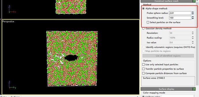
I am a graduate student majoring in glass. When I am using the alpha shape algorithm in Ovito’s Construct Surface Mesh, it is very difficult to determine the parameters, Probe sphere radius and Smooth level. Because glass contains multiple elements, I cannot determine which two elements’ nearest neighbor atomic distances should be used as the basis for detecting the radius of the sphere. So I would like to request your help and look forward to receiving your response。
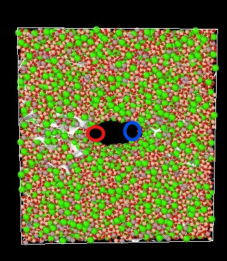
There is no universal rule to picking the “right” probe sphere radius. I would probably start with the smallest radius that fits in your void (either the blue or red circle in my crude drawing). Depending on the results It probably makes sense to slightly increase or decrease the radius from there.

Have you tried the Gaussian Density Method? It might work better for non crystalline materials (depending on their density and homogeneity).
Right, keep in mind that the results of the alpha-shape method generally depend on the probe sphere radius you choose. Be sure to report the exact radius in any publications that involve measuring surface area, solid volumes, or porosity.
What is your goal? Are you interested in determining the volume of the pore located at the center of the cell? If so, a good starting point would be to conduct a parameter study by systematically varying the probe sphere radius, as Daniel said. This approach will help you identify the optimal radius for accurately characterizing the pore volume.
Also, you might find the code example given here helpful:
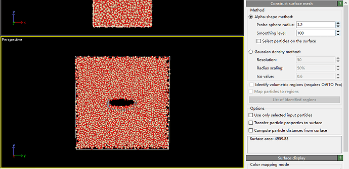
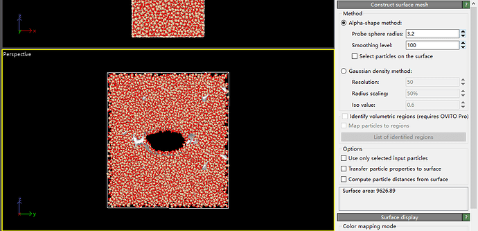
I’m glad to receive your answer. I’m sorry I didn’t express my goals clearly. I want to use the alpha shape method to calculate the difference in area of the same model before and after uniaxial stretching, in order to represent the area of cracks generated during the stretching process, as shown in the following two figures. I have found that the Probe sphere radius has a significant impact on this difference, so I hope to receive your help.
I’m glad to receive your answer. I’m sorry I didn’t express my goals clearly. I want to use the alpha shape method to calculate the difference in area of the same model before and after uniaxial stretching, in order to represent the area of cracks generated during the stretching process, as shown in the following two figures. I have found that the Probe sphere radius has a significant impact on this difference, so I hope to receive your help.
Following this post:
Plotting the “crack area difference” over different alpha shape radii can probably be used to converge to some useful result.
Alternatively, you have to determine a correct value for the radius based on visual inspection and domain knowledge. This is a question best discussed with your colleagues or supervisors as we cannot provide scientific consulting.
In any case you should report your probe sphere radius.
How do I determine the smooth level after determining a suitable probe radius? Because I couldn’t find a definitive method in the user manual. And I found that this parameter has an impact on the final crack area second only to the probe radius. We look forward to your reply.
Smoothing should be roughly shape and volume conserving. There is no single “correct” approach to smoothing, as it largely depends on your mesh topology, research goals, and personal preference. Based on experience, a smoothing factor around 10 typically yields reasonable results.
The smoothing method is adapted from Gabriel Taubin’s paper, “A Signal Processing Approach to Fair Surface Design”. For more details, please refer to the original publication.


