Dear Lammps users,
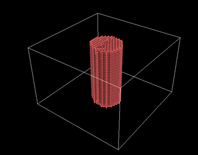
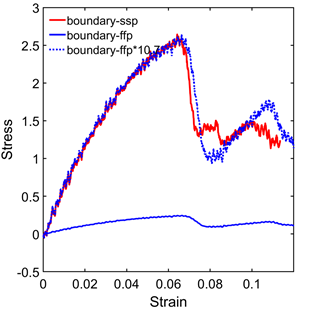
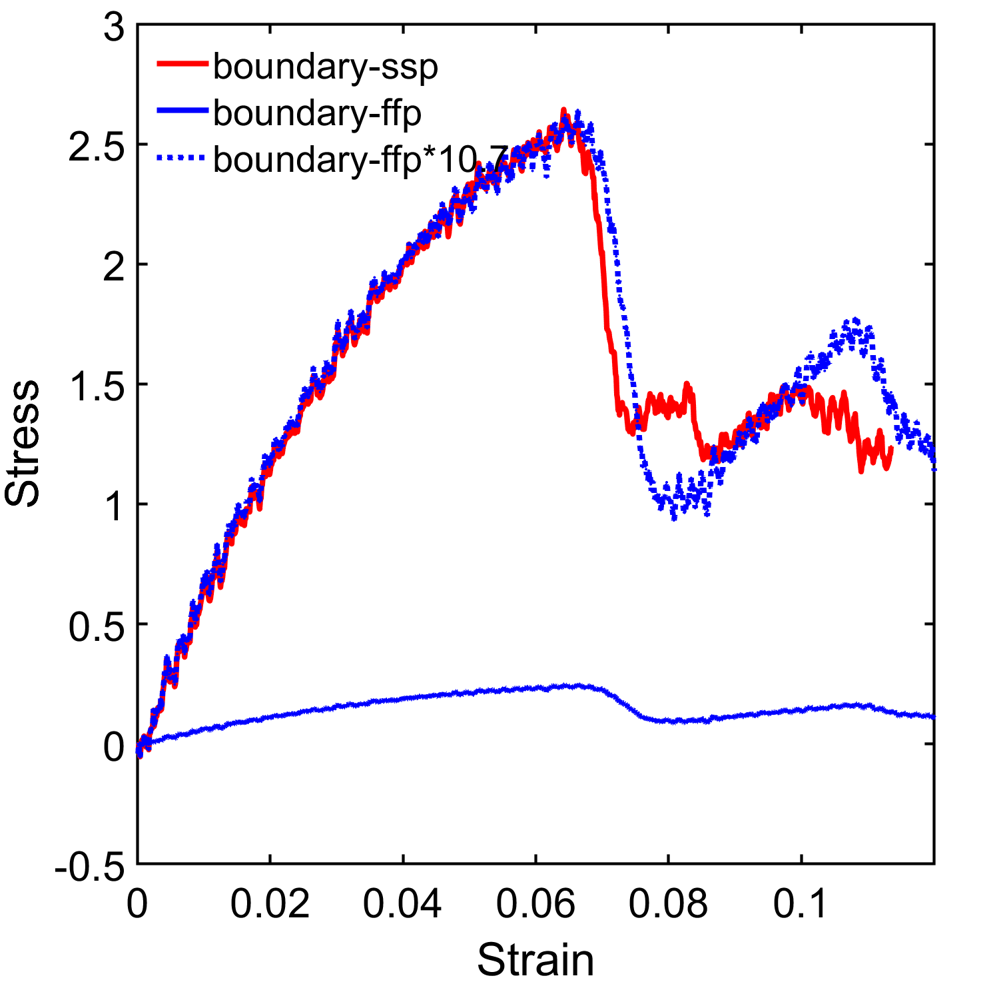
Hi, I am trying to perform tensile loading on a nanowire. As shown in the stress strain curve attached, when using free surface boundary on the lateral direction (ffp boundary), the stress is very small (ultimate stress<0.5GPa). When changing the lateral boundary condition to shrink-wrap (ssp boundary), the stress seems to be normal. the stress from ssp is 10.7 times larger than the ffp (the stress-strain matches perfectly during early stage between ssp and ffp*10.7). The boundary is sufficiently large and does not intersect with the structure during the simulation, as illustrated in the attached figure. Moreover, if I use the dumped snapshots from the ffp result as input and just do a run 0 without any fix, it outputs stress in the correct range. What could be the cause for this difference? Thank you inadvance.
My Input scripts
--------------- INITIALIZATION ------------------
clear
units metal
dimension 3
boundary s s p
atom_style atomic
variable temperature equal 300.0
------------------ ATOM DEFINITION -------------------
read_data nwdata_0_2.equil
mass 1 107.86
------------------------ FORCE FIELDS -----------------------
pair_style eam/alloy
pair_coeff * * CuAg.eam.alloy Ag
neighbor 2.0 bin
neigh_modify delay 10 check no
------------------------- Storing initial length -------------------------
variable length equal “lz”
variable L0 equal {length}
print "Initial Length, L0: {L0}"
------------------------- Tensile -------------------------
reset_timestep 0
thermo 100
thermo_style custom step temp pe pxx pyy pzz pxy pxz pyz
fix 1 all deform 1 z erate 0.001 units box
fix 2 all nvt temp {temperature} {temperature} 1
variable strain equal “(lz - v_L0)/v_L0”
variable p1 equal “v_strain”
variable p2 equal “-pxx/10000”
variable p3 equal “-pyy/10000”
variable p4 equal “-pzz/10000”
fix def1 all print 100 “{p1} {p2} {p3} {p4}” file stress_strain.txt screen no
run 250000
Lijie
Are you running in parallel? and if yes with how many MPI processes?
can you provide the logfiles of two runs with the different settings?
have you tried doing multiple runs where you reinitialize the atom velocities with different random seeds?
One more question. How do you compute “Stress” in your graph? In the LAMMPS input you are computing 3 numbers for x-, y-, and z-direction.
Hi Alex,
Thank you for responding. Yes, I am running in parallel with 16 MPI processes. The stress in the graph is Sigma_zz. I have tried different builds of lammps on different machines, but the ffp result is always too small. The Log files are attached.
I have not tried doing multiple runs with different random seeds. I have tried to have an additional nvt relaxation before the tensile loading, which did not help.
Lijie
logFFP.lammps (281 KB)
logSSP.lammps (282 KB)
Hi Alex,
Thank you for responding. Yes, I am running in parallel with 16 MPI processes. The stress in the graph is Sigma_zz. I have tried different builds of lammps on different machines, but the ffp result is always too small. The Log files are attached.
Thanks. After looking at your logs and also the LAMMPS source code, here is the explanation:
You can see the factor already in the thermo output. That is mostly due to how LAMMPS computes the pressure tensor.
It takes the negative of the (virial) stress tensor components and divides them by the volume of the simulation cell.
With fixed boundaries that volume is exactly like you provided it in your data file.
With shrinkwrap that will shrink to the extent of the volume that your atoms occupy.
But neither is really correct, since you have a free surface in x- and y- direction the real total volume of your system is infinity and therefore the pressure should technically be zero.
Now you can get access to the original stress tensor by using compute stress/atom to collect the per-atom values and then compute the sum of those via compute reduce.
see https://docs.lammps.org/compute_stress_atom.html This is the virial stress in the original stress*volume formulation that must be divided by the negative of the relevant volume to obtain the corresponding pressure component. However, that volume is not a well defined property at the atomic level.
Axel.
Isn’t it obvious that ffp and ssp will give different stress value since volume is different in two different boundary conditions.
Volumes of the physical model (nanowire) and box are different in both boundary conditions. If you consider nanowire volume in stress calculation, both boundary conditions are supposed to give same results, IMO.
Sanjib