My crystal is a metal-organic framework, and I want to use GULP to perform a series of optimizations. Before that, I think it’s necessary to make sure the code describes the crystal correctly.
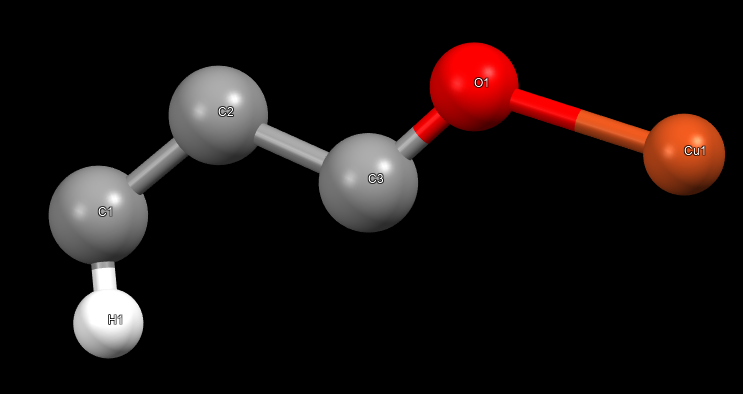
there are 6 atoms in the asymmetry unit, and the space group is 225, here is the structure of the asymmetry unit:
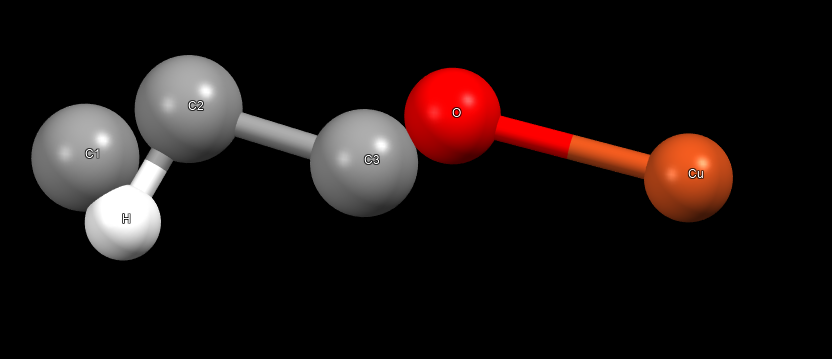
the bonding is wrong in the output asymmetric unit, e.g., there are 6 bond types in the origin cif file, but the output one has only 4; and the H should only connect to C1 but it also connect to C2 in the output cif.
I also tried to grow the crystal, but the bonds between asymmetric units are absent.
Does anyone know how to fix the bonding problem and how to make the asymmetric units connected?
my code: myfit.gin (3.6 KB)
and output file: output.got (61.6 KB)
and the GULP version is 6.2.0.
Thank you in advance.
Dear Wang,
The structure of your MOF is fine, which can be seen from adding “dist” to look at the distances in the structure. The issue is the specification of the bonds for fitting having the wrong numbers. It’s hard to get the numbers you need by hand since they refer to the full cell. The best way to see the bonding connectivity is to add the keyword “molq” to automatically generate bonds & then to dump it to the restart file using “dump connectivity”. This then provides information on the correct numbers & cell images. Of course if you fit the structure then you’re implicitly fitting the bonds as well anyway.
Regards,
Julian
Thank you for your reply. My problem has been resolved. This ‘dump’ command automatically generates over 900 bonds with the default bond type single.
now I want to change the bond type to resonent since parts of the bonds should be. then I used the option ‘bondtype’:
bondtype Cu core Cu core single
bondtype Cu core O core single
bondtype C1 core H core single exo
bondtype C2 core C1 core resonant cyc
bondtype C3 core C2 core single exo
bondtype O core C3 core resonant
however, it seems the bond type cannot be written to the dump file. secondly, I tried to just put the above lines in the input files after the ‘connect’ part to run fit, but the bond type in the output file didn’t change.
I think it’s impossible to revise the bond type by hand, do you have any idea to change the bond type automatically? thank you again.
I am afraid you need to generate a representation of your system in P1 space group , specify all bonds yourself an disable GULP bond creation. I am still not sure how to set up cross- cell bonds in this way.
Related question - why do you need to specify bond type ? It play rule only for some force fields (UFF). Eg. gaff/gaff2 or Dreidin recognize forces from atom types and ignores bond orders … Even for uff I belive you can specify the forces manualy = ignore order and let GULP find them.
As I can’t see your input I’m not sure what the issue is for your input. However, here is an simple example of how to automatically generate bonds and set the type using “bondtype” at the same time:
grad conp molmec bond
cell
25.8556 25.8556 25.8556 90 90 90
frac
Zn core 0.293477 0.293477 0.293477
C core 0.111460 0.250000 0.250000
C core 0.053860 0.250000 0.250000
C core 0.217510 0.217510 0.473430
O core 0.250000 0.250000 0.250000
O core 0.219370 0.219370 0.366110
H core 0.195600 0.195600 0.455200
space
F M -3 M
bondtype Zn Zn double
dump connect bondtest.res
In this example I use “molmec” to find all the bonds & use “bondtype” to set Zn-Zn bonds to be double bonds (NB this is just an example of how to use the command rather than suggesting that Zn-Zn double bonds are a sensible thing to have!). If you look in the restart file generated then you will see that the Zn-Zn bonds are indeed now dumped as being double bonds.
Hope that helps.
Julian
I saw the difference between ‘molq’ and ‘molmec’ is the latter subtracts the Coulomb terms, which I think I can add back in the restart file, and to do other calculations.
I have tried your example, and it works. I have attached my input file because I exactly followed your example, but my input file doesn’t work.
Dear Wang,
Apologies but there was a hiccup in the code for cases where there are 2 different atom types. I’ve now fixed this in the version 6.2 for download and in 6.3 which is now available.
Sorry for the issue, but hopefully this is now resolved.
Best regards,
Julian
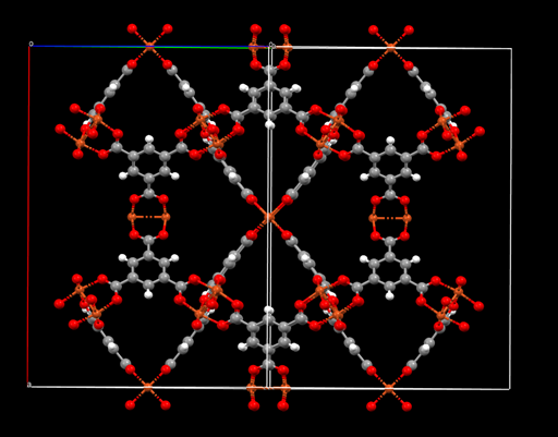
with the 6.3 version, I can output the cif file to visualize the crystal structure after optimization:
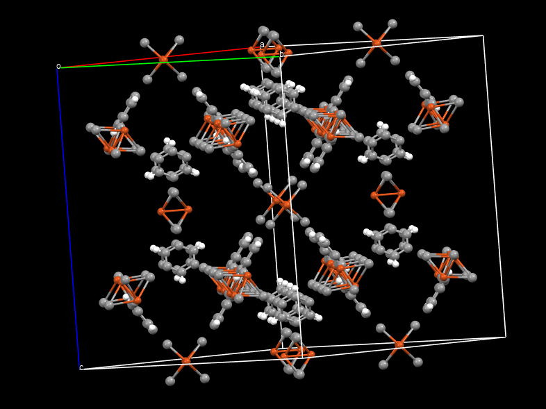
without charge, it properly reproduced the structure, but when I assigned the charges ( crystalvis.gin (8.8 KB)
), the outputted cif file is strange, even though I tried with other different types of charges.
this is the structure without charge:
this is the DDEC charges assigned:
Dear Wang,
If I run the input that you’ve posted, with or without adding uff4mof as the force field, then the structure blows up, as you can see from the energy heading towards minus infinity and all the ***** in the gradients. Therefore it’s not surprising that the final structure looks very odd if the force field isn’t optimising it to something sensible.
Regards,
Julian
it’s hard to believe that is due to the bad force field. I used the same charge and force field parameters in LAMMPS, and the structure is fine after energy minimization and through all simulations. Anyway, it means the force field makes sense, although it is not very accurate to reproduce some properties.
I am just surprised that GULP cannot optimize the structure with this widely-used force field, can you let me know what is the reason this force field failed in the GULP ( but it worked in other MD simulators), how can I make sure what kind of force field works in GULP? it is necessary to use the force field derived from the ab initio method?
Dear Wang,
Over the years we’ve done quite a few comparisons of GULP vs LAMMPS for optimisation and in our experience GULP will always optimise structures in fewer cycles and to higher precision than LAMMPS given the same force field. This is not an outrageous claim of one piece of software being better than the other; it just comes down to the fact that GULP uses analytic second derivatives with BFGS whereas LAMMPS uses only first derivative-based optimisation techniques, and so the result is just what would be expected based on the choice of method. This is not to say that things are faster in CPU since this depends on other factors (e.g. size of the system and the scaling of the Hessian evaluation, distance of the minimum from the initial structure, etc). The key point here is “given the same force field”. Have you checked that the energy and forces for the initial structure are identical (to within the precision of unit conversion factors) in LAMMPS and GULP? If they aren’t, then this is the reason for the different behaviour. The first thing to do is to work through all the components of the force field energy checking that they match, otherwise you are not comparing the same force field parameters. You could post your LAMMPS input files and output for a single point (with the energy breakdown turned on) and then it will be possible for us to spot any differences.
Regards,
Julian
here are the files to run the same force field in lammps ( data.data (273.1 KB) lammps.in (833 Bytes)
) and gulp ( fitAB1.gin (12.5 KB) fitAB1_o14_conp.got (48.8 KB)
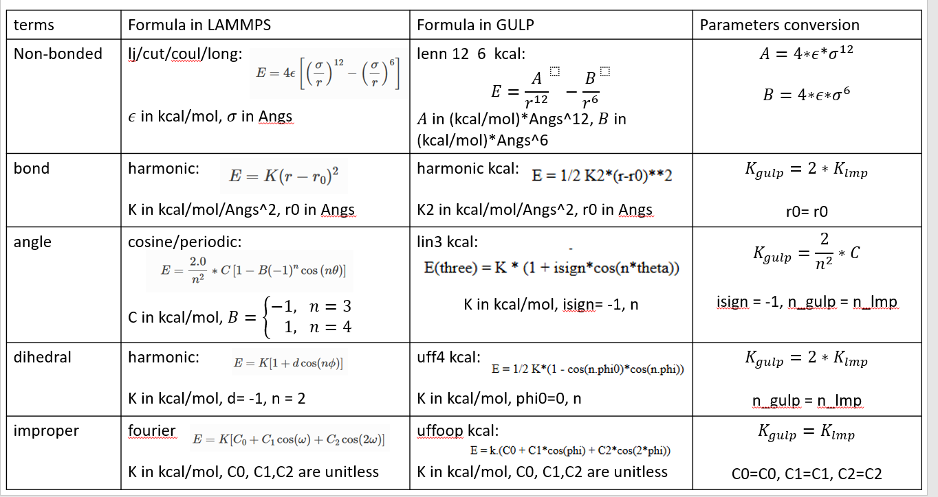
), the conversion of the parameters is quite complex and easy to make mistakes, so I also attached the general rules for my case:
meanwhile, I think I also kept other settings the same in both lammps and gulp, for example, I used ‘special_bonds lj/coul 0.0 0.0 0.5’ in lammps to exclude 1-2,1-3 and to scale 1-4 interactions, which is considered in gulp via ‘o14’ as well.
but the output still shows me the warning ‘Not all configurations optimised successfully in relaxed fit’
furthermore, as the manual says: ‘The choice of appropriate algorithm for minimisation depends on the size of the system and number of variables. it will become necessary to use first the unit Hessian approach and then ultimately the conjugate gradients method as N continues to increase.’, I was wondering if using only the default BFGS minimizer for my case with 156 atoms in a primitive cell really works or not, as the sum of square is extremely large at the beginning.
Dear Wang,
I’m afraid I don’t have time to to through all details of your work since this is the responsibility of who ever is leading/supervising the project to decide what the force field should be. If you want to check things against LAMMPS to make sure they are the same just go through one potential at a time and compare the energies/forces for the initial structure.
One thing to note is that you don’t have any charges, which is unusual for a force field of such materials & so this won’t help the model. You should also check that the initial structure optimises before doing a relaxed fit others you’ll get warnings/errors.
The final point about not using the Hessian when N gets large. You only have the asymmetric unit of a small system & so this definitely doesn’t apply when start getting into the thousands of atoms then you should think about this.
Regards,
Julian
for the connectivity output with “molmec” and “dump connect bondtest.res”, for example, this is the list of the connectivity:
connect 2 1 1 -1 0
connect 4 3 0 0 -1
connect 8 6 -1 0 1
connect 9 5 0 1 -1
connect 11 7 1 0 0
connect 12 10 0 -1 0
connect 13 1 0 0 0
connect 14 2 0 0 0
connect 15 3 0 0 0
connect 16 4 0 0 0
connect 17 5 0 0 0
connect 18 6 0 0 0
connect 19 7 0 0 0
connect 20 8 0 0 0
How can I know which atom type these atom numbers are if I have a connectivity list with hundreds of lines? since I need to use “fbond”, which uses atom numbers to specify the bond length.
Answer is in the first line of the help text describing the use of the option:
@@connect
Topic : connect
Type : Option
Format : connect atom1 atom2 <type_of_bond>
Default : If imageX, imageY, imageZ are not specified then take the nearest
: image.
Use : Forces a bond to be formed between atom1 and atom2 where atom1 and
: atom2 are the numbers of atoms in the full unit cell.